| I’ve never been one to enjoy table top puzzles, yet I love to examine the way mechanical things fit together. Manipulating parts to see how they interrelate to form an operational system is a pastime I very much enjoy. In fact, I spend many evenings at my work bench doing just this. I often become so engrossed in the activity I forget what time it is. The result is yet another night without TV. So sad…
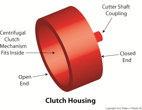
Last week we looked at how a centrifugal clutch mechanism operates when it’s coupled to a gasoline engine shaft spinning at idle speed, and then we depressed the engine throttle trigger to speed things up. Let’s now introduce a new component called the clutch housing to see how it interfaces with the clutch mechanism to drive the cutter head in a grass trimmer. Figure 1
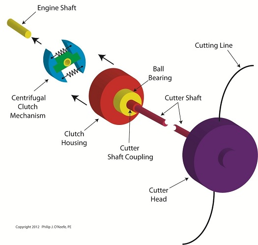
The clutch housing shown in Figure 1 resembles a rather short cup. One end is open, the other closed. Figure 2 shows the closed end of the clutch housing connected to the cutter shaft’s coupling. On the cutter shaft coupling resides a ball bearing which enables the clutch housing to both spin freely and act as a support for the clutch housing. The open end of the clutch housing allows the clutch mechanism to fit neatly inside. Figure 2
Next time we’ll put the assembly shown in Figure 2 into operation. First we’ll examine how the centrifugal clutch mechanism and clutch housing operate with the engine at idle speed, then compare that to the engine operating at actual cutting speed. ____________________________________________
|
Engineering Expert Witness Blog
Published by Philip J. O'Keefe, PE, MLE


