| When I was in engineering school in the mid 1970s microprocessor chips were still a fairly new concept. Scientific calculators were the size of a brick back then, and they weighed almost as much, and there were no personal computers.
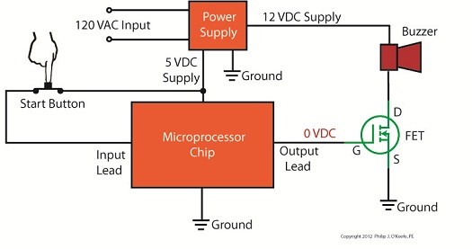
I remember doing homework on the UNIVAC 1108 mainframe computer at school. To program it I had to sit at a monster of a keypunching machine for which I punched an endless array of holes into paper cards. These holes acted as the programming logic to instruct the computer what functions to perform. The 1108 computer’s mainframe was so huge it was housed in an adjoining room the size of a house. Since the 1980s advances in microprocessor technology have increased computing power and dramatically reduced the size of components, making things like laptops, smart phones, and sophisticated electronic products possible. Last time we began looking at my design solution for the control of a machine which developed medical x-ray film and made use of a microprocessor chip to automate its operation. A field effect transistor (FET) acts as a digital control interface between its 5 volt direct current (VDC) microprocessor and a 12 VDC buzzer. Figure 1 shows what happens when someone presses the button to put everything into action and the microprocessor starts timing. Figure 1
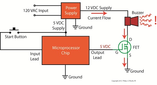
With the button depressed the chip senses 5 VDC from the power supply on its input lead. This in turn signals the computer program to turn the product on. The program then begins counting down the minutes, all the while maintaining a 0 voltage output from the chip’s output lead. With no voltage present on its G lead, the FET does not permit electrical current to flow from the 12 VDC supply, through the buzzer, through D and S, and down to electrical ground. The buzzer remains silent. Figure 2Figure 2 shows what happens when the program begins its 40-minute warming sequence. The chip raises the output lead voltage to 5 VDC and applies it to G, then the FET permits electric current to flow through it to ground from the 12 VDC supply and the buzzer. Now supplied with power, the buzzer sounds. Then, per programming instructions, after 2 seconds the program shuts off the voltage in the chip’s output lead, current is cut off, and the buzzer goes silent. Next time we’ll see how an FET can be used as an interface between a microprocessor and another higher powered device, that of a 120 VAC motor that’s used to move x-ray film through a series of processes within the developer.
____________________________________________ |
Archive for July 1st, 2012
Transistors – Digital Control Interface, Part III
Sunday, July 1st, 2012Tags: 12 VDC, 5 VDC, alarm, automate, buzzer, current, D, design solution, digital control, electric relay, electrical design, electronics, engineering expert witness, FET, field effect transistor, forensic engineer, G, hardware design, machine control, medical product, microprocessor chip, MOSFET, motor, power supply, programming logic, pushbutton, S, voltage
Posted in Engineering and Science, Expert Witness, Forensic Engineering, Innovation and Intellectual Property, Personal Injury, Product Liability | Comments Off on Transistors – Digital Control Interface, Part III


