| When my daughter was seven she found out about Ohm’s Law the hard way, although she didn’t know it. She had accidentally bumped into her electric toy train, causing its metal wheels to derail and fall askew of the metal track. This created a short circuit, causing current to flow in an undesirable direction, that is, through the derailed wheels rather than along the track to the electric motor in the locomotive as it should.
What happened during the short circuit is that the bulk of the current began to follow through the path of least resistance, that of the derailed wheels, rather than the higher resistance of the electric motor. Electric current, always opportunistic, will flow along its easiest course, in this case the short, thick metal of the wheels, rather than work its way along the many feet of thin metal wire of the motor’s electromagnetic coils. With its wheels sparking at the site of derailment the train had become an electric toaster within seconds, and the carpet beneath the track began to burn. Needless to say, mom wasn’t very happy. In this instance Ohm’s Law was at work, with a decidedly negative outcome. The Law’s basic formula concerning the toy train would be written as: I = V ÷ Rwhere, I is the current flowing through the metal track, V is the track voltage, and R is the internal resistance of the metal track and locomotive motor, or in the case of a derailment, the metal track and the derailed wheel. So, according to the formula, for a given voltage V, when the R got really small due to the derailment, I got really big. But enough about toy trains. Let’s see how Ohm’s Law applies to an unregulated power supply circuit. We’ll start with a schematic of the power supply in isolation.
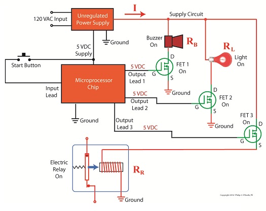
Figure 1The unregulated power supply shown in Figure 1 has two basic aspects to its operation, contained within a blue dashed line. The dashed line is for the sake of clarity when we connect the power supply up to an external circuit which powers peripheral devices later on. The first aspect of the power supply is a direct current (DC) voltage source, which we’ll call VDC. It’s represented by a series of parallel lines of alternating lengths, a common representation within electrical engineering. And like all electrical components, the power supply has an internal resistance, such as discussed previously. This resistance, notated RInternal, is the second aspect of the power supply, represented by another standard symbol, that of a zigzag line. Finally, the unregulated power supply has two output terminals. These will connect to an external supply circuit through which power will be provided to peripheral devices. Next time we’ll connect to this external circuit, which for our purposes will consist of an electric relay, buzzer, and light to see how it all works in accordance with Ohm’s Law. ____________________________________________ |
Archive for August 7th, 2012
Transistors – Voltage Regulation Part III
Tuesday, August 7th, 2012
Tags: burn, buzzer, current flow, DC, derail, derailed wheels, direct current, electric motor, electric relay, electric toaster, electrical engineering, electromagnetic coils, engineering expert witness, forensic engineer, internal resistance, light, locomotive, metal track, ohm, Ohm's Law, power supply, resistance, schematic, short circuit, sparking, supply circuit, track, unregulated power supply circuit, voltage source, volts
Posted in Engineering and Science, Expert Witness, Forensic Engineering, Innovation and Intellectual Property, Personal Injury, Product Liability | Comments Off on Transistors – Voltage Regulation Part III


