|
We’ve been discussing the advantages of using limiting resistors within Zener diode regulating circuits to lessen the probability of circuit failure. Today we’ll continue our discussion, focusing on the Zener diode’s advantages and disadvantages. See Figure 1.

Figure 1
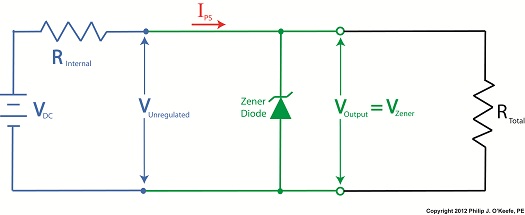
Figure 1 discloses the simplicity of a voltage regulator employing a Zener diode. There are only two components, a limiting resistor, RLimiting, and the Zener diode itself, which also makes the entire assembly cost effective to manufacture.
Despite the obvious advantages, there is one major disadvantage to the Zener diode voltage regulator. Ironically, the limitation imposed by RLimiting on the current IPS itself creates an operational dilemma. When electronic devices are connected to the output terminals of the regulator, RLimiting and its current-limiting action becomes a disadvantage. See Figure 2.

Figure 2
The amount of current I available to flow through to electronic devices is limited, sometimes too much, and the net result is that the Zener diode voltage regulator can only be used to power electronic devices drawing small amounts of current. It is unacceptable for many applications, such as powering kitchen appliances or flat screen TVs.
Next time we’ll see how to improve upon the Zener diode voltage regulator circuit by adding a transistor. This will eliminate the road block imposed by RLimiting, thus allowing higher, but still regulated, current to flow through to the output terminals.
____________________________________________ |
 Engineering Expert Witness Blog


