|
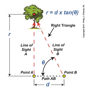
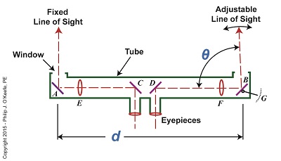
Last time we touched on the fact that humans require instruments to facilitate the optical measurement of distance to faraway objects, such as is represented by r in Figure 1. Figure 1 Today we’ll take a look at the mirrors inside an optical rangefinder, one of the devices that’s commonly used to measure great distances. The internal workings of an optical rangefinder are shown in Figure 2. Figure 2 The rangefinder’s body is a straight tube containing fixed mirrors, A, C, and D, and an adjustable mirror, B. Mirrors A and B in Figure 2 are analogous to Points A and B in Figure 1. For the sake of our example, we’ll say that the distance d in Figure 2 is equal to the distance d in Figure 1. This distance is three feet. The rangefinder functions similarly to a pair of binoculars, but with a twist — literally. Its four internal mirrors redirect the straight-ahead perspective that’s provided by the eyepieces into sideways orientations. Sight is deflected by mirrors C and D off to the left and right, respectively, as represented by red dashed lines. Finally, the lines of sight are once again aligned into straight-ahead orientations as they reflect off mirrors A and B and are guided out the openings at either end of the tube. Adjustable mirror B‘s line of sight is positioned at an angle that’s represented by the Greek letter θ, a symbol commonly used to represent angles in mathematics, engineering, and science. This angle is formed between mirror B’s line of sight and the horizontal line of sight traversing the expanse between mirrors D and B. The reason mirror B is an adjustable mirror is so that the line of sight extending from the opening at its location can converge into the line of sight provided by mirror A. Mirror B is manually manipulated until the image seen through it becomes one with A‘s image. Until this convergence takes place two separate images are seen through A and B. Next week we’ll see what happens when the images converge, and we’ll cover the remaining components within an optical rangefinder, items E, F, and G. ____________________________________
|
Engineering Expert Witness Blog
Published by Philip J. O'Keefe, PE, MLE


