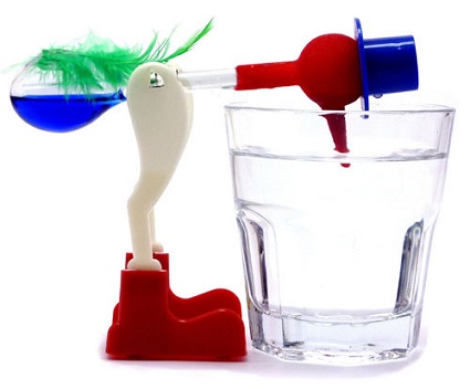
You know that little red guy that bobs in and out of a glass of water, seemingly without end? He’s an example of a non-perpetual motion device, because even he will eventually come to a stop due to something known as uncontrollable factors. Uncontrollable factors are a hindering factor in coal fired power plants, as well, most notably by a measure of efficiency known as heat rate.
Uncontrollable Factors At Play
The term heat rate is industry jargon for gauging how efficiently a coal fired power plant is operating. We previously learned that heat rate can be affected by things like missing thermal insulation on pipes and equipment. Of course missing insulation can easily be corrected because it’s directly under human control, but heat rate can be affected by many factors we can’t do anything about, known as uncontrollable factors.
Human fallibility is behind the phenomenon of uncontrollable factors, and because we are less than 100% accurate and efficient, so is anything that we make. At their best utilitycoal fired power plantshave an overall efficiency of between 30 and 40 percent, which means 60 to 70 percent of the stored energy inside coal is wasted and doesn’t go towards generating electricity.
Unfortunately there’s nothing we can do to eliminate these waste factors until improvements are made in the present level of technology. When we look through a microscope to view microbes we’re limited by the accuracy of the equipment, and in a similar way we are limited in everything we do as humans by the equipment we’ve built. That includes energy efficiency within power plants.
We’ll start identifying the uncontrollable factors that affect power plant performance next time.
Last time, we learned how a solenoid valve operates to create different compressed air flow paths through passageways within its valve body. These different air flow paths are created by opening and closing an electrical switch to de-energize and energize a solenoid mounted on the valve body. Now let’s see how engineers use a solenoid valve in a food manufacturing plant to move a depositor’spneumatic actuator piston back and forth with compressed air pressure.
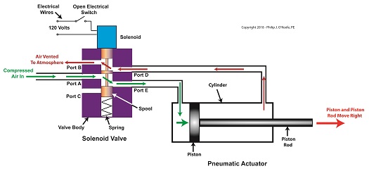
Consider the pneumatic actuator on the depositor’s scotch yoke. With the solenoid valve’s electrical switch opened, the valve’s spool is pushed up in the valve body by a spring to create air flow paths between Ports A and E and Ports D and B. If compressed air is fed into Port A and the left side of the pneumatic actuator’s cylinder is connected to Port E, then the air pressure moves the actuator’s piston to the right. But, for the actuator piston to move freely to the right, the right side of the cylinder is connected to Port D on the valve body. As the piston moves to the right, it forces air out of the right side of the cylinder, through Port D, through the valve body, and out through Port B to be vented to the atmosphere.
The De-energized Solenoid Valve Operates a Pneumatic Actuator
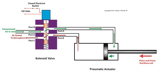
With the solenoid valve’s electrical switch closed, the spool is pushed down in the valve body by the solenoid, to create air flow paths between Ports A and D and Ports E and C. If compressed air is fed into Port A and the right side of the pneumatic actuator’s cylinder is connected to Port D, then the air pressure moves the actuator’s piston to the left. But, for the actuator piston to move freely to the left, the left side of the cylinder is connected to Port E. As the piston moves left, air is forced out of the left side of the cylinder, through Port E, and vented to the atmosphere through Port C.
The Energized Solenoid Valve Operates a Pneumatic Actuator
So, in review, opening the solenoid valve’s electrical switch causes the pneumatic actuator piston to move right. Closing the switch causes the piston to move left. But there is a problem with this setup. Operating an electrical switch by hand to deposit jelly filling on thousands of pastries can get tiring after a while. Next time, we’ll see how the valve’s solenoid can be automatically turned on and off by an industrial control system.
Previously, we looked at the components of a solenoid valve, which is an electro-mechanical device that is commonly used by engineers to operate pneumatic actuators with compressed air. These solenoid valve components include a solenoid and a valve body. We also looked at an illustration of an example solenoid valve. Its valve body had five ports for connections to compressed air pipes. Now, let’s see how the example solenoid valve operates to create different compressed air flow paths between its ports.
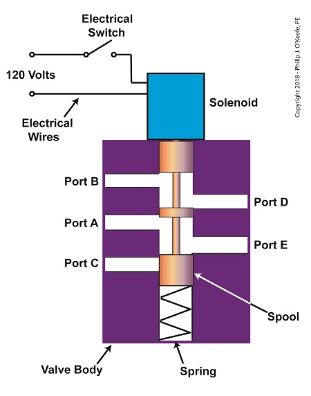
When the solenoid valve’s electrical switch is opened, the flow of electrical current from its 120 Volt supply is interrupted. This results in the solenoid’s wire coil being de-energized. As such, the coil generates no magnetic field. Without the magnetic field, there is no downward force exerted on the solenoid’s plunger and the valve body’s spool. A spring at the bottom of the valve body acts upon the spool to force it upward in the valve body and hold it there. With the spool in the upward position, two compressed air flow paths are created in the valve body. One path extends through a passageway connecting Ports D and B, and the other extends through a passageway connecting Ports A and E. The spool seals off the passageway leading to Port C.
The Solenoid Valve’s Operation: De-energized
When the electrical switch is closed, the 120 Volt supply is connected to the valve’s solenoid. This results in the solenoid’s coil becoming energized. When that happens, the electrical current flowing through the coil generates a magnetic field. The magnetic field forces the plunger and spool in the downward direction. The spool overcomes the spring force and moves into a downward position within the valve body. In this position, the spool creates a new pair of compressed air flow paths. These paths remain as long as the current flows through the solenoid’s coil. One compressed air flow path extends between Ports A and D. The other path extends between Ports E and C. The spool seals off the passageway leading to Port B.
The Solenoid Valve’s Operation: Energized
When the electrical switch opens, the solenoid’ coil again becomes de-energized. The magnetic field collapses, and no downward force remains on the plunger and spool. The spring forces the spool back up in the valve body. Once again, a pair of compressed air flow paths is created between Ports D and B, and between Ports A and E. The passageway to Port C is sealed off by the spool.
Next time, we’ll see how the example solenoid valve’s operation is applied to move the piston back and forth in a depositor’s pneumatic actuator.
So far in this series of articles, we have talked about pneumatic actuators that move jelly filling through a depositor on a pastry production line in a food manufacturing plant. These actuators have pistons with piston rods that create linear motion. The direction of this motion depends on which side compressed air is admitted to the piston inside the actuator. Now, let’s begin discussing a device known to engineers as a solenoid valve. These valves are used to selectively admit compressed air to either side of the pneumatic actuator’s piston, and thus, change the direction of the actuator’s linear motion.
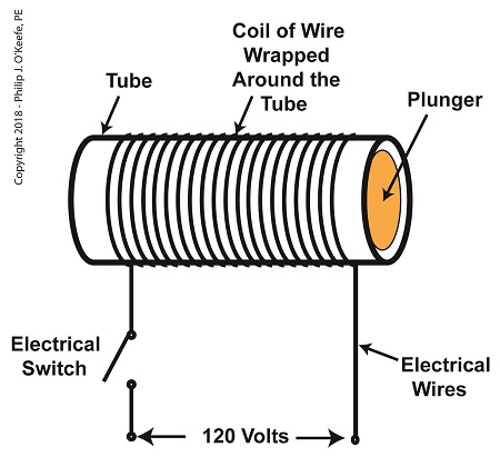
As a solenoid valve’s name implies, a key component is a solenoid. A solenoid consists of a tube, having a coil of wire wrapped around its exterior. Electrical wires extend from the coil to an electrical switch and a voltage supply of, for example, 120 Volts. Inside the tube, there is a steel plunger that is free to move. When the switch is open, the coil is de-energized. That is, no electric current flows from the voltage supply through the coil of wire.
A De-Energized Solenoid
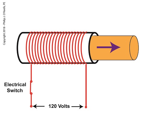
When the electrical switch is closed, the coil becomes energized. As electrical current flows through the coil, a magnetic field is created in the tube. This field forces the steel plunger out of the tube. The magnetic field and force on the plunger remain as long as the switch is closed.
An Energized Solenoid
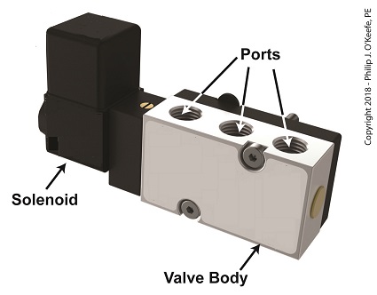
A solenoid valve consists of a solenoid that is attached to a metal valve body. The solenoid is typically enclosed in a plastic or metal housing. The valve body contains various ports. The ports are threaded holes for the connection of compressed air pipes.
A Solenoid Valve
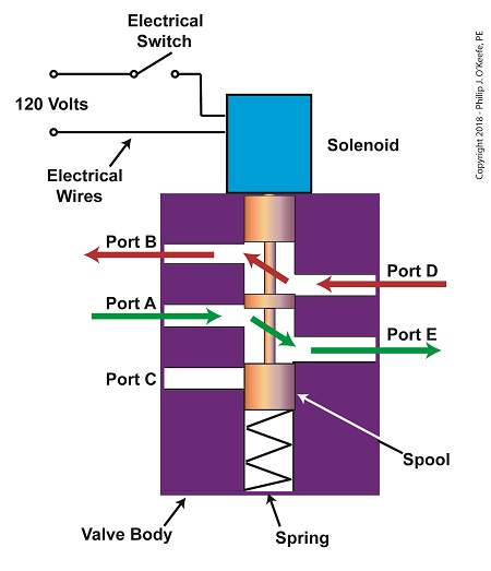
The solenoid’s plunger is attached to spool in the valve body. The spool is free to move within the valve body past passage ways extending from the ports. In the following illustration, the solenoid valve contains five ports, designated A through E.
The Solenoid Valve’s Components
Next time we’ll see how the five port solenoid valve operates to create different compressed air flow paths between its ports.
In my previous article, I introduced a mechanism known to engineers as a Scotch Yoke. It converts linear motion of a pneumatic actuator into rotary motion. With regard to the jelly filling depositor on a pastry production line, the Scotch Yoke converts the pneumatic actuator’s linear motion into the rotary motion needed to operate the depositor’s diverter valve. Now, let’s follow the Scotch Yoke’s motion in this application.
When the pneumatic actuator’s piston is all the way to the left, the Scotch Yoke’s slider is all the way to the left on the guide rod. The slider pin is at the top of the slot in the yoke mechanism. The diverter valve is positioned to create a path for the jelly so it can be emptied from the pump through the nozzle.
The Depositor’s Scotch Yoke Slider Is Full Left
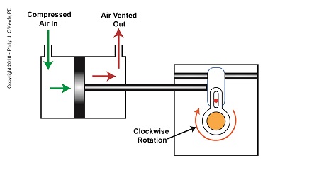
As compressed air is introduced to the left side of the actuator’s piston, the piston moves to the right, and the slider also moves to the right. As this happens, the slider pin begins to move in the yoke mechanism’s slot, and the diverter valve shaft begins to rotate clockwise.
The Depositor’s Scotch Yoke Clockwise Rotation
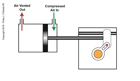
After the piston moves all the way to the right, and the diverter valve shaft stops its clockwise rotation. The diverter valve is positioned to create a path between the pump and hopper so the pump can suck in jelly from the hopper. When the pump is full of jelly, compressed air is introduced to the right side of the piston.
The Depositor’s Scotch Yoke Slider Is Full Right
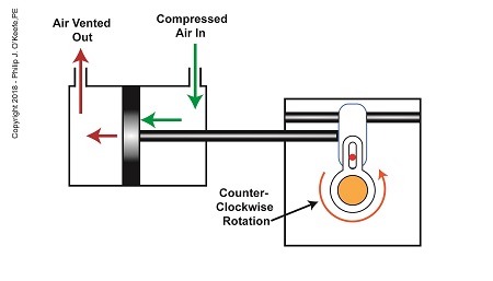
As compressed air is introduced to the right side of the actuator’s piston, the piston moves to the left, and the Scotch Yoke’s slider also moves to the left. As this happens, the slider pin begins to move in the yoke mechanism’s slot, and the diverter valve shaft begins to rotate counterclockwise.
The Depositor’s Scotch Yoke Counterclockwise Rotation
After the piston moves all the way to the left, the diverter shaft stops its counterclockwise rotation. The diverter valve is once again positioned to create a path so the jelly can flow from the pump through the nozzle. After all the jelly is emptied from the pump, compressed air is introduced to the left side of the piston to repeat the previously described motion.
But what selectively admits compressed air to either the right or left of the pneumatic actuator’s piston? Next time, we’ll find out when we discuss a device called a solenoid valve.
Last time, we learned how a pneumatic actuator was connected to a depositor’s positive displacement piston pump so that it could extract jelly filling from a hopper, and deposit it through a nozzle onto a passing pastry. The pneumatic actuator imparted linear motion to the pump during this process. Since the pistons in the actuator and pump both move in a straight line, it was very easy and straightforward to connect the actuator to the pump.
For the depositing process to work, we must have an additional actuator to rotate the diverter valve as the pump operates. The valve changes the flow path of the jelly between the hopper and the nozzle. More specifically, the valve must rotate clockwise to create a flow path between the hopper and the pump while the pump extracts jelly from the hopper.
The Diverter Valve Rotated Clockwise
When the pump is full of jelly, the diverter valve must rotate counter-clockwise to create a flow path between the pump and the nozzle. This path allows the pump to empty its contents trough the nozzle.
The Diverter Valve Rotated Counter-Clockwise
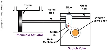
Although the diverter valve’s motion is rotary, it can be operated with the linear motion of a pneumatic actuator. To convert the linear motion of the actuator to the rotary motion needed to operate the valve, we can employ a device known to engineers as a Scotch Yoke.
The Depositor’s Scotch Yoke
In the Scotch Yoke, the pneumatic actuator’s piston rod is connected to a slider. As the piston moves back and forth in the pneumatic actuator, the slider is free to move back and forth along a fixed guide rod. A pin is located on the slider. The pin loosely engages a slot in the yoke mechanism. As the slider moves, the pin can move freely in the slot. The yoke mechanism is rigidly attached to the rotating diverter valve shaft.
Next time, we’ll look at the rotary motion of the Scotch Yoke as the pneumatic actuator piston moves to the right and then to the left during the jelly depositing process.
Last time we learned how pneumatic actuators impart linear motion to machines. Now, let’s see how the pneumatic actuator is connected to the depositor’s pump. The connection imparts linear motion to the pump so it draws in jelly filling from the supply hopper and sends it streaming out of the nozzle onto a passing pastry.
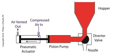
On the depositor, the pneumatic actuator’s piston rod is connected to the pump’s piston. As such, the pistons in the actuator and pump move together. When compressed air is admitted to the right side of the pneumatic actuator, the pistons in actuator and pump move to the left. As the pump’s piston moves to the left, a vacuum is formed in the pump. This vacuum sucks the jelly out of the hopper, through the diverter valve, and into the pump as shown below.
The Depositor’s Pneumatically Actuated Pump
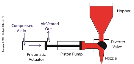
Once the pump is full of jelly, compressed air is admitted to the left side of the actuator piston. The pistons in actuator and pump move to the right as the compressed air expands and presses against the piston in the actuator. As the pump’s piston moves to the right, pressure builds up on the jelly in the pump. The pressure empties the jelly from the pump. The jelly is forced from the pump, back through the diverter valve, and it streams out of the nozzle as shown below.
The Depositor’s Pneumatic Actuator Empties the Pump
For the pumping process to take place, the diverter valve must be rotated to first allow jelly to flow from the hopper. The diverter valve must be rotated again to allow jelly to flow through the nozzle. Next time, we’ll see how a pneumatic actuator is attached to a mechanical linkage that rotates the diverter valve.
Last time we learned that a fruit jelly depositor in a food manufacturing plant is an example of a positive displacement pump at work. Today we’ll see how pieces of equipment on the depositor, known as a pneumatic actuators, work. Pneumatic actuators do not come in contact with the jelly flowing through the depositor. In other words, no jelly flows through the actuators. The jelly only flows through the transfer valve and positive displacement pump as we saw last time. The pump and valve can’t move by themselves. So, they need some device to set them in motion. That’s where the pneumatic actuators come into play. They impart movement to the pump and transfer valve to get the jelly flowing from the hopper and down through the nozzle and onto the pastry.
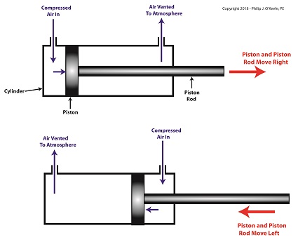
A pneumatic actuator is a device that operates using compressed air. Compressed air, from an external air compressor, enters into a tube in the actuator known as a cylinder. Inside the cylinder is a piston that can move along the length of the tube. Attached to the piston is a piston rod which extends to the outside of the cylinder.
When compressed air is introduced into the cylinder on the left side of the piston, it forces the piston and piston rod to move towards the right side of the cylinder. But, air must be vented out to atmosphere from the right side of the piston for this movement to occur. If no venting took place, trapped air to the right of the piston will get squeezed between the piston and the right end of the cylinder. When the air gets squeezed, it becomes pressurized. The pressure will impede the movement of the piston.
Likewise, when compressed air is introduced into the cylinder on the right side of the piston, it forces the piston and piston rod to move towards the left side of the cylinder.
The Depositor’s Pneumatic Actuator
So, depending on which end compressed air is admitted to the pneumatic actuator’s cylinder, the piston rod will move to the left or the right. In engineering terms, the actuator imparts linear motion to machines. In other words, the piston rod moves back and forth in a straight line.
Next time, we’ll see how the pneumatic actuator is connected to the depositor’s pump to impart the linear motion that draws jelly from the supply hopper and sends it streaming out of the nozzle onto a passing pastry.
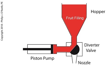
Our last blog introduced a project I oversaw while acting as a design engineer in a food manufacturing plant. The objective was to deposit fruit jelly into raw pastry dough as it whizzed along a production line conveyor belt before being sent off for baking. A special piece of equipment known as a depositor would be required to meet this challenge, and we’ll take a look at how one functions today. In fact, a jelly depositor acts very much as a human heart, as they’re both examples of positive displacement pumps.
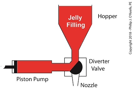
A depositor is a device specifically made for the food industry. It consists of a hopper to hold the product to be deposited, in this case fruit jelly, which is discharged by the hopper into a rotating diverter valve and then on to a positive displacementpiston pump. See below.
A Jelly Depositor is a Positive Displacement Pump
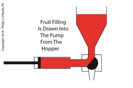
When the diverter valve rotates, a passageway opens to allow jelly to flow from the hopper into the piston pump. A pneumatic actuator, a device we’ll discuss in more depth next time, moves the pump’s piston to the left, away from the diverter valve, which allows the filling to be released into the pump from the hopper. At the end of the piston’s travel a set quantity of fruit jelly filling is drawn into the pump’s housing, just enough to fill one pastry. See below.
The Depositor Draws Filling Into The Pump
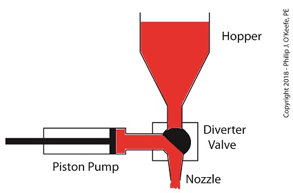
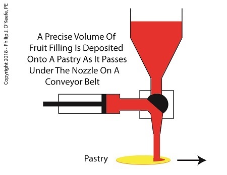
When the diverter valve rotates in the opposite direction, a passageway opens inside the valve that allows jelly filling to move from the pump to the nozzle. As the piston moves back toward the diverter valve the filling is forced out of the pump, through the nozzle, and into the pastry dough. The pump’s piston moves back and forth, that is, away from and then towards the transfer valve, ushering a set quantity of jelly filling through the mechanism each time. See below.
The Depositor Deposits The Filling
Now that we know how the depositor works, next time we’ll discuss the pneumatic actuator’s role in the filling process.
Last time we learned that the human heart functions as the greatest of all positive displacement pumps, moving a set quantity of blood through it at precise intervals during its operating cycle. Today we’ll begin our exploration into how positive displacement pumps are used in industry, specifically within a food manufacturing plant.
At one point in my career I was employed as a design engineer in a food manufacturing plant. The plant was owned by the leading manufacturer of bakery products in the United States, responsible for supplying restaurants, bakeries, and grocery stores with finished and partially finished pastry goods that they would then resell. The plant produced vast amounts of puff pastry dough products, all of which were formed and filled with various fillings while zipping along on a production line conveyor belt. One of the products was a fruit filled pastry in which the belt moved so quickly, depositing fruit fillings into the dough by hand would be impossible, resulting in a frenzied mess similar to what Lucy encountered when she worked in a candy factory.
Clearly, an automated machine would work better in this and other scenarios. We’ll see how one known as a depositor functions on a food pastry line next time.