|
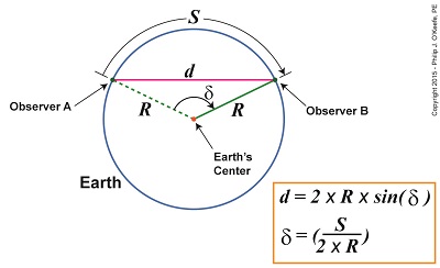
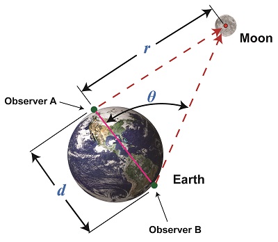
Last time we learned that early scientists used Earth as a huge optical rangefinder to gauge the distance, r, between it and the moon. But before they could put to use our by now very familiar distance calculating formula they needed to first determine the distance, d, between their observation positions. This distance is known within mathematical circles as a chord and is represented by the pink solid line in Figures 1 and 2. A chord is simply a straight line drawn between any two points on a circle, in this case the distance, d, between our observers of the moon. Its length can be determined mathematically if the Earth’s radius, R, and the curved distance, S, between Observers A and B are known. Calculating d was done with relative ease by putting Earth’s circular geometry and principles of mathematics to use. The formula that will accomplish this is shown in Figure 2’s inset box. And here’s the distance calculating formula, yet again: r = d × tan(θ) Figure 2 You will note that Figure 2 features a new symbol, δ , which represents a new angle, and a new trigonometric term, sin( ), or sine. To understand how the angle δ is formed, imagine a green line of length R that extends from Earth’s center to its surface. This is Earth’s radius, as determined by Eratosthenes. The end attached to Earth’s center pivots to allow R‘s other end to travel along Earth’s surface. It travels a path between Observers A and B, represented by curved line S. The angle δ is formed between the dashed green line, which represents R‘s starting point, and R‘s solid green line, which represents its finishing point at Observer B’s location. Figure 2 shows that the angle δ is calculated by dividing S by 2 × R . This numerical value is then entered into a scientific calculator, and when we press the sin button we’re provided with the sine value for angle δ. It should be noted that this is measured in radians, a measuring system typically associated with circles (rather than the more familiar degrees), in order to obtain the correct answer for d. Scientific calculators easily switch between the two modes. Follow this link if you’d like to learn more about radians. Now the Earth is relatively close to the moon, a mere 238,900 miles, and using it as an optical rangefinder to gauge distance to the moon is relatively straightforward. But can it be used to judge the distance to its sun, a whopping 93,000,000 miles away? We’ll see next time why it can’t and what alternate method must be used.
____________________________________
|
Archive for April, 2015
Determining Chord Length on Circle Earth
Tuesday, April 28th, 2015Optically Measuring Cosmic Distances
Wednesday, April 22nd, 2015|
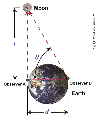
Last time we learned that the bigger an optical rangefinder, the better its accuracy in measuring distant objects. Today we’ll take that concept a step further when we discover how Earth itself was used by ancient scientists to gauge its distance to the moon. Today’s blog will be strewn with embedded links to past blogs in this series, all of which have been building up to our understanding of gravity, a complex subject with many pieces to its puzzle. There are a few remaining pieces to be placed which will be covered in future blogs, but I promise we’ll get there. Long before Edmund Halley’s time, scientists used the Earth as a huge optical rangefinder. In doing so they employed the principles of parallax and trigonometry to obtain reasonably accurate measurements of the distance between Earth and its nearest neighbors, starting with the moon. See Figure 1. The illustration shows how it was done. Two observers armed with telescopes viewed the moon from opposite sides of the earth. Their lines of sight are represented by dashed lines, and together with the solid pink line which represents the distance between them, d, a right triangle was formed. Because Observer B was situated on the other side of the globe, his line of sight fell at an angle relative to Observer A’s, due to the Principle of Parallax. The angle that formed at the point in the triangle at which B was situated we’ll call θ. The fact that a right triangle was formed at Observer A’s observation point will enable our ancient scientists to use principles of trigonometry and parallax in their quest to find the distance to the moon. Follow this link to a refresher blog on the subject, Using Parallax to Measure Distance. At precisely the same moment the moon moved into Observer A’s telescopic line of sight, Observer B adjusted his telescope to center the moon within it. Observer B then duly measured the angle θ formed with a protractor, just as would be done with a rangefinder. If you’ve been reading along in this series, this setup might look familiar to you. In fact, the two mirrors of a military optical rangefinder work in exactly the same way as our two observers looking at the moon. Follow this link to a refresher on the internal workings of a rangefinder. Once the angle θ’s value had been determined, it was used to calculate the distance r between Earth and the moon with the same equation we’ve been using to measure distances using military optical rangefinders: r = d × tan(θ) As far as our moon observers go, the only variable left for them to determine before they are able to measure Earth’s distance to the moon is d, the distance between their viewing positions on Earth. We’ll see how to solve for d next time, when we put the Earth’s geometry to work for us.
____________________________________
|
Optical Rangefinders, Bigger is More Accurate
Tuesday, April 14th, 2015|
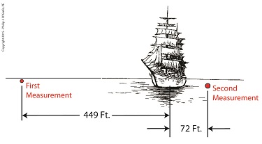
Last time we touched on the fact that bigger is better when it comes to using a rangefinder to measure extremely long distances. Today we’ll expand on that theme and discover how bigger is indeed more accurate. Returning to our previous example, we’re still trying to find the distance to that ship on the horizon. We’ve got two rangefinders at our disposal, one short, one long, and the measurements provided by them are vastly different. Which is correct? To find out, we’ll hypothesize that we’ve taken the time to meticulously measure the distance the hard way, with a really long tape measure. Doing so, we find the actual distance to the ship is 5280 feet. We can now compare the actual measured distance to the measurements taken with our two rangefinders and compare their accuracy: Rangefinder One = 5729 feet – 5280 feet = 449 feet Rangefinder Two = 5208 feet – 5280 feet = -72 feet The smaller rangefinder results in a difference, or error, of 449 feet, while the bigger results in a difference of 72 feet. It’s clear that the bigger rangefinder gets us closer to the actual measurement taken by tape measure, so it’s the most accurate. The obvious conclusion is that the bigger the rangefinder used, the smaller the error factor. That’s because as the length of the rangefinder increases, the smaller the angle θ becomes, a situation which results in the tangent of θ moving farther away from rather than closer to 90°, all of which translates to more accuracy in our rangefinder’s measurements. Put another way, the bigger the rangefinder, the less likelihood there is of its angle θ‘s tangent hovering near 90° and becoming asymptotic, an undesirable outcome for reasons explained in a previous blog in this series. Next time we’ll see how early astronomers were able to arrive at relatively accurate calculations of the distances between Earth and other heavenly bodies by using the parallax effect produced by the world’s largest optical rangefinder, Planet Earth itself. ____________________________________
|
Optical Rangefinders, Why Bigger is Better
Monday, April 6th, 2015|
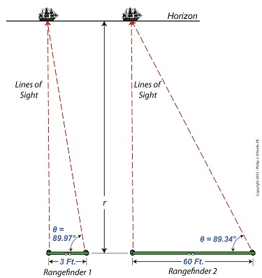
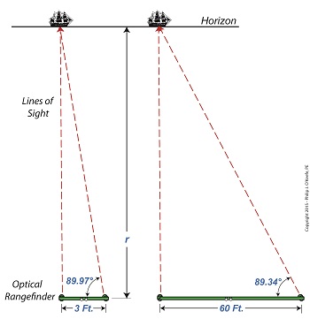
Last time we introduced the fact that ultra fine gradations must be applied to a rangefinder’s indicator gauge in order to make accurate measurements of extremely long distances. Today we’ll see how using a bigger rangefinder effectively solves this problem. Figure 1 illustrates the subject. The left side shows what happens when attempting to use a small rangefinder to measure the distance to that distant ship on the horizon. The right side shows how the situation is improved by using a large rangefinder, which serves to decrease the angle θ. Figure 1 You see it all boils down to the angle θ. When d is extremely short in comparison to the measured distance r, the angle θ creeps ever closer to becoming 90°, a situation which severely impacts the rangefinder’s accuracy due to the impact on the tangent of θ. For a refresher on that see last week’s blog. Let’s see what the situation looks like numerically. The smaller rangefinder has a length, d, equal to 3 feet. Using it we measure θ to be 89.97°. Plugging these numbers into the rangefinder distance measuring formula, we measure the distance to the ship to be: r = d × tan(θ) r = 3 feet × tan(89.97°) r = 5729 feet Now let’s take a second measurement with the bigger rangefinder on the right. This one has a length d equal to 60 feet. You might be asking yourself, Do they really come that big?? Yes, before radar technology came on the scene to take their place, it was possible to find rangefinders as big as 60 feet in length! Using the larger rangefinder we find θ is equal to 89.34° and the distance to the ship is calculated to be: r = d × tan(θ) r = 60 feet × tan(89.34°) r = 5208 feet Why are the measurements between the two rangefinders so different? Which one is more accurate? In short, bigger is better. We’ll see why next week. ____________________________________
|
