Posts Tagged ‘blower’
Friday, April 21st, 2017
|
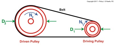
Last time we saw how pulley diameter governs speed in engineering scenarios which make use of a belt and pulley system. Today we’ll see how this phenomenon is defined mathematically through application of the Pulley Speed Ratio Formula, which enables precise pulley diameters to be calculated to achieve specific rotational speeds. Today we’ll apply this Formula to a scenario involving a building’s ventilating system.
The Pulley Speed Ratio Formula is,
D1 × N1 = D2 × N2 (1)
where, D1 is the diameter of the driving pulley and D2 the diameter of the driven pulley.
A Pulley Speed Ratio Formula Application
The pulleys’ rotational speeds are represented by N1 and N2, and are measured in revolutions per minute (RPM).
Now, let’s apply Equation (1) to an example in which a blower must deliver a specific air flow to a building’s ventilating system. This is accomplished by manipulating the ratios between the driven pulley’s diameter, D2, with respect to the driving pulley’s diameter, D1. If you’ll recall from our discussion last time, when both the driving and driven pulleys have the same diameter, the entire assembly moves at the same speed, and this would be bad for our scenario.
An electric motor and blower impeller moving at the same speed is problematic because electric motors are designed to spin at much faster speeds than typical blower impellers in order to produce desired air flow. If their pulleys’ diameters were the same size, it would result in an improperly working ventilating system in which air passes through the furnace heat exchanger and air conditioner cooling coils far too quickly to do an efficient job of heating or cooling.
To bear this out, let’s suppose we have an electric motor turning at a fixed speed of 3600 RPM and a belt-driven blower with an impeller that must turn at 1500 RPM to deliver the required air flow according to the blower manufacturer’s data sheet. The motor shaft is fitted with a pulley 3 inches in diameter. What pulley diameter do we need for the blower to turn at the manufacturer’s required 1500 RPM?
In this example known variables are D1 = 3 inches, N1 = 3600 RPM, and N2 = 1500 RPM. The diameter D2 is unknown. Inserting the known values into equation (1), we can solve for D2,
(3 inches) × (3600 RPM) = D2 × (1500 RPM) (2)
Simplified, this becomes,
D2 = 7.2 inches (3)
Next time we’ll see how friction affects our scenario.
Copyright 2017 – Philip J. O’Keefe, PE
Engineering Expert Witness Blog
____________________________________ |
Tags: belt, blower, blower impeller, cooling coils, drive belt, driven pulley, driving pulley, electric motor, engineering, heat exchanger, mechanical power transmission, pulley, pulley speed, Pulley Speed Ratio Formula, RPM, ventilating system
Posted in Engineering and Science, Expert Witness, Forensic Engineering, Innovation and Intellectual Property, Personal Injury, Product Liability | Comments Off on A Pulley Speed Ratio Formula Application
Tuesday, June 28th, 2016
|
Pulleys are simple devices with many uses, and as an engineering expert, I’ve often incorporated them into mechanical designs. They’re used in machinery to transmit mechanical power from electric motors and engines to devices like blowers and pumps. Another common usage for pulleys is to aid in lifting. There are two types of pulleys for this purpose, simple or compound. We’ll start our discussion off by looking at the simple type today.
The simple pulley may have been an advanced application of the wheel. It consists of a furrowed wheel on a shaft with some device for pulling threaded through it. The pulley wheel supports and guides the movement of a rope, cable, or other pulling device around its circumference. The pulling device runs between a pull-ee and pull-er, that is, the object to be moved and the source of pulling power, with the pulley itself situated somewhere between them.
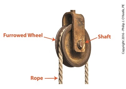
Simple Pulley
Pulleys are believed to have first been used by the Greeks as early as the 9th Century BC. We’ll look into how they put them to use next time.
Copyright 2016 – Philip J. O’Keefe, PE
Engineering Expert Witness Blog
____________________________________ |
Tags: belt, blower, cable, compound pulley, electric motors, engineering expert, engines, mechanical design, pulley, pumps, simple pulleys, transmit mechanical power
Posted in Engineering and Science, Expert Witness, Forensic Engineering, Innovation and Intellectual Property, Personal Injury, Product Liability | Comments Off on Simple Pulleys
Sunday, February 19th, 2012
| Electric motors are everywhere, from driving the conveyor belts, tools, and machines found in factories, to putting our household appliances in motion. The first electric motors appeared in the 1820s. They were little more than lab experiments and curiosities then, as their useful potential had not yet been discovered. The first commercially successful electric motors didn’t appear until the early 1870s, and they could be found driving industrial devices such as pumps, blowers, and conveyor belts.
In our last blog we learned how a latched electric relay was unlatched at the push of a button, using red and green light bulbs to illustrate the control circuit. Now let’s see in Figure 1 how that circuit can be modified to include the control of an electric motor that drives, say, a conveyor belt inside a factory.

Figure 1
Again, red lines in the diagram indicate parts of the circuit where electrical current is flowing. The relay is in its normal state, as discussed in a previous article, so the N.O. contacts are open and the N.C. contact is closed. No electric current can flow through the conveyor motor in this state, so it isn’t operating. Our green indicator bulb also does not operate because it is part of this circuit. However current does flow through the red indicator bulb via the closed N.C. contact, causing the red bulb to light.
The red and green bulbs are particularly useful as indicators of the action taking place in the electric relay circuit. They’re located in the conveyor control panel along with Buttons 1 and 2, and together they keep the conveyor belt operator informed as to what’s taking place on the line, such as, is the belt running or stopped? When the red bulb is lit the operator can tell at a glance that the conveyor is stopped. When the green bulb is lit the conveyor is running.
So why not just take a look at the belt itself to see what’s happening? Sometimes that just isn’t possible. Control panels are often located in central control rooms within large factories, which makes it more efficient for operators to monitor and control all operating equipment from one place. When this is the case, the bulbs act as beacons of the activity taking place on the line. Now, let’s go to Figure 2 to see what happens when Button 1 is pushed.

Figure 2
The relay’s wire coil becomes energized, causing the relay armatures to move. The N.C. contact opens and the N.O. contacts close, making the red indicator bulb go dark, the green indicator bulb to light, and the conveyor belt motor to start. With these conditions in place the conveyor belt starts up.
Now, let’s look at Figure 3 to see what happens when we release Button 1.

Figure 3
With Button 1 released the relay is said to be “latched” because current will continue to flow through the wire coil via one of the closed N.O. contacts. In this condition the red bulb remains unlit, the green bulb lit, and the conveyor motor continues to run without further human interaction. Now, let’s go to Figure 4 to see how we can stop the motor.

Figure 4
When Button 2 is depressed current flow through the relay coil interrupted. The relay is said to be unlatched and it returns to its normal state where both N.O. contacts are open. With these conditions in place the conveyor motor stops, and the green indicator bulb goes dark, while the N.C. contact closes and the red indicator bulb lights. Since the relay is unlatched and current no longer flows through its wire coil, the motor remains stopped even after releasing Button 2. At this point we have a return to the conditions first presented in Figure 1. The ladder diagram shown in Figure 5 represents this circuit.

Figure 5
Next time we’ll introduce safety elements to our circuit by introducing emergency buttons and motor overload switches.
____________________________________________ |
Tags: blower, closed contact, control panel, control room, conveyor belt, electric current flow, electric motor, electric relay, engineering expert witness, equipment operator, factory, forensic engineer, indicator lamp, industrial control, ladder diagram, latched circuit, motor control, motor drive, N.C., N.O., normal state, normally closed, normally open, panel indicator, pump, push button, safety, start pushbutton, stop pushbutton
Posted in Engineering and Science, Expert Witness, Forensic Engineering, Innovation and Intellectual Property, Personal Injury, Product Liability, Professional Malpractice | Comments Off on Industrial Control Basics – Electric Motor Control
Sunday, May 22nd, 2011
| When something is said to be the “heart of the operation,” one usually imagines that it is integral to whatever is being discussed, and it is probably centrally located. The human heart fits this description well. This amazing organ, centrally located within your chest cavity, moves blood, nutrients, oxygen, and carbon dioxide through your body with amazing efficiency. During a twenty four hour period it can pump as much as 2,000 gallons of blood through 6,000 miles of arteries, veins, and capillaries.
At the heart of a local exhaust ventilation system is its fan. Like the human heart, it is a model of efficiency. It first creates a vacuum in the intake hood, which is strategically located at a pollution source, pulling in contaminated air and leading it through ductwork. Sometimes the fan leads the air to a filter or other air cleaning equipment, but eventually the dirty air is exhausted through a stack leading outdoors.
There are two main types of fan, axial and centrifugal. You’re probably most familiar with the axial type, because they’re the type commonly used in tabletop, box, and oscillating fans in your home. These have blades that look like a propeller on an airplane, and they work by drawing air straight through the fan. As helpful as they are within a personal setting, axial fans are not typically used in local exhaust ventilation systems because the electric motor that drives the blades is in the path of airflow. This setup can create a problem if the air flowing over the motor contains dust and flammable vapor. Dust can cause the motor to get dirty and overheat. Flammable vapor can ignite if the motor wiring fails and creates an electrical arc.
Because of the technical difficulties presented by an axial type fan, centrifugal fans are what are most often used in industrial settings. One such fan is shown in Figure 1.

Figure 1 – Centrifugal Fan
The blades of a centrifugal fan are fully enclosed in air tight housing. This housing keeps any dust or fumes from leaking out into the building. The electric motor that drives the fan can be safely located outside of this housing, where it is dust-free and there are no flammable vapors. If you look inside the housing you will see that the moving part, known as the impeller, resembles a squirrel cage. See Figure 2.

Figure 2 – Centrifugal Fan Impeller
This impeller is made up of many blades, set up within a wheel configuration. When an electric motor causes the wheel to rotate, air is made to move off the blades and out of the impeller due to centrifugal force. This air is sent crashing into the fan housing, shown in Figure 1, which is curved like a spiral to direct the air into an outlet duct which is connected to ductwork that leads to the exhaust stack. As air leaves the impeller, more air rushes into its center from the inlet duct to occupy the empty space that’s been created. Hence, as long as the motor keeps spinning the impeller, air will flow through the fan.
In order for all this to work effectively, the centrifugal fan must be the right size, one that is capable of providing enough suction to capture contaminated air at the hood source, then overcoming the resistance to air flow that is presented by ductwork, filters, and other air cleaning devices. Because air resistance factors such as these impede the fan’s ability to move air through the system, the fan must be of sufficient strength make up for these factors. To size up the right centrifugal fan for the job, engineers must calculate the resistance to airflow that is expected to be encountered, and to do this they use data supplied by manufacturers of component parts, as well as tabulated data that is readily available in engineering handbooks. Just as a lawn mower engine won’t provide sufficient energy to power a car, an undersized fan won’t be able to move air through a system which is beyond its capacity limit.
Next time, we’ll finish our series on local exhaust ventilations systems by looking at the last component in the system: the exhaust stack.
_____________________________________________

|
Tags: air cleaner, air resistance, airflow, axial fan, blower, centrifugal fan, dirty air, ductwork, dusty air, electric motor, engineering expert witness, exhaust stack, fan, fan blade, filert, flammable vapor, forensic engineer, impeller, local exhaust ventilation system, pollution, squirrel cage, ventilation
Posted in Engineering and Science, Expert Witness, Forensic Engineering, Innovation and Intellectual Property, Personal Injury, Product Liability | 2 Comments »
Sunday, May 15th, 2011
| I was out in the garage today spray painting, a job I would have preferred to have done outdoors, but alas, it was raining. It wasn’t a big job, and I probably didn’t spend more than about an hour doing it, but by the time I was done I was all too aware of how noxious the chemical fumes were that were put out by my aerosol spray can. I had thought that with all the garage doors open and a good cross breeze going through I’d be spared the unpleasant smell. Now imagine this all on a much larger scale, say an industrial setting, where massive spray painters are used all day long.
We’ve been talking for awhile now about filtration, from fabric filters to cyclones, and how they are most effective when integrated into a local exhaust ventilation system. These filtration devices are great for the removal of airborne particles like dust, but they don’t do a good job removing chemical vapors like paint fumes, much in the same way as a dust mask wouldn’t have made my spray painting job any less smelly. This week we’ll focus on filtration capable of addressing the special challenges presented by chemical vapors in the air.
Chemical vapor contaminants can be separated from good air trapped in a local exhaust ventilation system by way of an air cleaner in a process known as absorption. In this instance, just like with our smelly goldfish tank, the media can consist of activated carbon, a carbon created by intense heating of substances like bituminous coal, wood, or coconut shell. The heat removes everything except carbon and creates myriads of tiny pores throughout. These pores give activated carbon tremendous surface area, meaning lots of nooks and crannies for chemical molecules to get lodged in. And when I say “lots” of nooks and crannies, I mean it. One pound of granular activated carbon has enough pores to give it a surface area of 125 acres! As the air-vapor mixture passes over the huge surface area, chemical vapors are absorbed by combining chemically with the carbon. Jamb packing surface area into a small space, as activated carbon does, creates a media capable of absorbing vast amounts of chemical molecules for a long time. As effective as this system is, the carbon pores will eventually become saturated with contaminants, and when it does, it is easily addressed. Simply replace the media with fresh carbon.
Another means of removing harmful vapors from the air is through the use of an air cleaner employing temperature as its means of filtration. I’ll bet you’re asking how that works, and here’s an example you can relate to. It’s a hot, humid day, and the only thing standing between you and total discomfort is a glass of ice water. As you eagerly lift the glass to your lips, you notice the glass is wet on the outside, so wet that it’s actually dripping. In the stupor caused by your heat exhaustion you may for a moment think that the glass is actually leaking, but you soon realize that the water has accumulated on the outside of the glass because the hot, humid air that is making you so uncomfortable has also come into contact with the cold surface of the glass. When the water vapor in the atmosphere hits the cool of the glass filled with ice, it condenses into droplets. This condensation process stops when the glass temperature equalizes to that of the temperature in the surrounding air. Air cleaners can make use of the same phenomenon to filter contaminants. In their case the contaminated air mixture is cooled to the point where the humidity and chemical vapors present condense together to form a liquid, and the liquid is then drained out for proper disposal.
That’s it for our look at filters and air cleaners. To sum things up, remember that there are a variety of factors that have to be considered when selecting filters and air cleaning devices. These include the volume of air flowing through the system, the concentration of contaminants in the air, the chemical and physical properties of the contaminants, the hazards associated with the contaminants, and the emissions standards established by federal, state, and local environmental regulations.
Next time we’ll explore the workhorse of a local exhaust ventilation system, its fan.
_____________________________________________

|
Tags: absorption, activated carbon, air cleaner, air filter, blower, carbon filter, carbon pores, carbon surface area, chemical vapor, condensation, condensed liquid, cyclone separator, ductwork, dust collection, dust particles, engineering expert witness, fan, forensic engineer, forensic investigation, fumes, hood, local exhaust ventilation system, mechanical separator, spray paint, water droplets
Posted in Engineering and Science, Expert Witness, Forensic Engineering, Personal Injury, Product Liability | 2 Comments »
Monday, May 9th, 2011
|
We’ve been talking about mechanical filtration, like the type used by fish tanks. Now we’ll consider another type, the “cyclone.” It’s something which most of us have become very familiar with, thanks to a British bloke and his awesome vacuum that “…won’t lose suction!” His invention makes use of the principles of cyclone technology, and as effective as it is used in vacuums, it’s equally impressive used in local exhaust ventilation system applications. A cyclone that has been incorporated within this type of system is shown in Figure 1.

Figure 1 – Local Exhaust Ventilation System With Cyclone
Here’s how it works. A local exhaust ventilation system draws in corrupted air by means of a strategically placed hood, and its fan pulls the captured air and dust mixture through ductwork and into the cyclone. The cyclone is shaped like a cone standing upright on its small end. A cutaway view is shown in Figure 2.

Figure 2 – Cutaway View of a Cyclone
When a quickly-moving air and dust mixture gets drawn into the cyclone by the fan, the mixture is forced to spiral down into the cone by the shape of the inlet passage. Because dust particles are heavier than air molecules, they tend to separate due to centrifugal force. The heavier dust particles are sent crashing into the sloping sides of the cone. They then slide down to the bottom of the cone, where they will eventually fall through the bottom and into a waiting trash bin. The lighter air tends to stay in the center of the cyclone and is eventually drawn out by the fan through the outlet passage.
Unfortunately, cyclones are not 100% efficient when it comes to removing dust from the air. Their efficiency depends on many factors, including the shape of the cyclone, the speed of the flow going through it, and the weight of the dust particles. In any case, there’s always going to be some dust that will escape along with the air that’s being exhausted to the building’s exterior through the exhaust stack. If necessary, this air can be cleaned further before being released into the atmosphere by the use of additional filtration located within the ductwork between the cyclone and the fan.
That wraps up our discussion on dust removal through mechanical filtration. Next time we’ll look at systems capable of removing chemical vapors.
_____________________________________________
|
Tags: blower, centrifugal force, cone, cyclone, cyclone separator, duct, ductwork, dust, dust particles, engineering expert witness, exhaust stack, fan, filter, forensic engineer, hood, local exhaust ventilation system, spiral, vacuum
Posted in Engineering and Science, Innovation and Intellectual Property, Personal Injury | Comments Off on Industrial Ventilation – Local Exhaust Ventilation Filters and Air Cleaners II
Sunday, May 1st, 2011
|
My wife is an aquarist, meaning she keeps aquariums. Three of them. Each contains a different variety of fish housed within its own unique liquid environment. One of these is a 35 gallon tank containing three goldfish. These fish have two unique characteristics that make them especially noteworthy, they are extremely hardy and extremely dirty. Hardly a week can go by between tank changes before the water quality starts to deteriorate, evidenced by cloudy, stinky water. It’s the kind of stink that makes a passerby in the area exclaim, “Who used the bathroom and didn’t turn on the exhaust fan!” Thank goodness for activated carbon. With its proper placement inside the aquarium’s filtration system a cleaner, fresher environment is delivered, both to fish inside the tank and the humans who watch them from outside. Put the carbon in the wrong compartment, however, and the water quality plummets back to its original fetid state within a matter of days.
As is true with the proper care of goldfish, it is often necessary within an industrial environment to remove contaminants before the air that contains them is once again dispersed into the general environment. This is where filters and air cleaners come in. They’re generally placed inside the ductwork, somewhere between the hood and fan. Their job is to ensure a good, clean outcome, usually through an external exhaust of some sort. Local exhaust ventilation systems begin with a precisely positioned hood at the source of contamination and end with an exhaust stack located outside the building. Some airborne contaminants being released from the stack are deemed unsafe for the environment, and outdoor air quality standards promulgated by state and federal Environmental Protection Agencies limit their release back into the atmosphere. For this reason the proper use of filtration and air cleaners is crucial.
Airborne contaminants are in the form of dusts and vapors. If the issue to be addressed comes in the form of dust, then filters and mechanical separators are commonly used. Filters, like the atmospheric conditions they are meant to address, come in many configurations. They are typically positioned within the local exhaust ventilation system ductwork, as shown in Figure 1 below.

Figure 1 – Local Exhaust Ventilation System With Filter
The fan draws in air and dust through the strategically positioned hood, located at the source of contamination, then follows a course through ductwork, passing through a filter along the way. The filter contains media with holes tiny enough to allow for air to pass through, but small enough to stop dust particles. The cleaned air is then drawn out of the filter by a fan, which finally exhausts it into an externally positioned stack.
Next time we’ll continue our discussion on filtration devices by examining a cyclone. And no, I don’t mean the famous vacuum cleaner, although the methodology is similar.
_____________________________________________

|
Tags: activated carbon, air cleaner, air quality standards, airborne contaminants, blower, cyclone separator, duct, ductwork, dust, dust particles, engineering expert witness, environmental regulations, EPA, exhaust stack, fan, filter, filter media, forensic engineer, hood, local exhaust ventilation system, mechanical separator, vacuum cleaner
Posted in Engineering and Science | 1 Comment »
Sunday, April 10th, 2011
| My wife often says I’m the worst cook she knows. This doesn’t really bother me too much, because she’s the best cook I know, and she keeps me well fed. But there are times that I have to fend for myself in the kitchen, and this sometimes results in a foul smelling mess plastered all over the stove. Lucky for me we have a nice exhaust hood, and it usually manages to suck out the odor before my wife gets home.
Local exhaust ventilation systems, like the vent over my stove, work much the same way in an industrial setting, albeit on a larger scale. This type of ventilation system gets its name because its action is quite specific, localized to contain exhaust air from a particular area. They’re routinely placed as close as possible to the source of contaminants, and they are able to work quickly to capture and expel chemical vapors, dusts, and fumes, before they spread. This type of ventilation is effective for other reasons, too, because it helps keep down heating and cooling costs. Instead of treating an entire building for ventilation issues, the problem can be nipped in the bud at its source. In many situations, local exhaust ventilation is preferred over dilution ventilation systems for these very reasons.
A basic local exhaust ventilation system is comprised of a duct, a fan, and a hood as shown in Figure 1 below. One end of the duct is attached to the intake of the fan. The other end of the duct is attached to the hood. The duct can be rigid or flexible. The hood is positioned in the workplace near the source of contaminants.

Figure 1 – Basic Local Exhaust Ventilation System
This local exhaust ventilation system operates by much the same principle as the one generally governing the movement of liquids and gases. If you’re a regular reader of this blog, you’ll remember me writing that liquids and gases always flow from areas of higher pressure to those of lower pressure. Well, the air within the room has pressure principles at play as well, and the air within a given work area is at atmospheric pressure. When the fan is introduced into the scenario, a vortex is created within the duct which is less than that of the atmospheric pressure in the room. This difference in pressures causes the room air to flow into the ventilation duct along with its contaminants. The room air and contaminants flow out through the ventilation system, where they are then exhausted outside of the building.
But because room air is being drawn into the ventilation system, provisions must be made to supply enough replacement air. Without the proper ratio of air moving in to that moving out, a ventilation system will not work properly. In other words, the suction created by the local ventilation system could cause the pressure in the room to drop below atmospheric pressure. This could cause the higher atmospheric pressure outside the room to bear down on doors, making them difficult to open. Worse yet, contaminants could back up into the room, causing workers to get sick.
Now that we’ve covered the basics of local exhaust ventilation, we can move on to its five constituent elements and a discussion of their design. We’ll do that next week.
_____________________________________________ |
Tags: air flow, airborn contaminants, blower, ductwork, engineering expert witness, exhaust hood, fan, forensic engineer, HVAC, industrial ventilation, local exhaust ventilation, makeup air, toxic fumes
Posted in Engineering and Science, Expert Witness, Forensic Engineering, Personal Injury, Product Liability | Comments Off on Industrial Ventilation – Local Exhaust Ventilation


