| My first car was a used 1963 Dodge 880. It was reliable for the most part, but one day when I stepped on the brake in a supermarket parking lot, nothing happened. I began to roll down an incline, and I struggled to steer around the maze of parked cars in the lot. After what seemed to be an eternity I managed to navigate my way out of the lot into an adjacent cornfield. The soft ground and corn stalks finally brought me to a stop. I later discovered that the reason my brakes failed is because their linings had completely worn away.
Like the brakes in cars, centrifugal clutch shoes also have linings as shown in Figure 1. Brake linings are typically made of a rough, high friction materials, such as ceramic compounds. These materials are bonded to the brake shoes, or in the case of clutches, to the clutch shoes. When centrifugal force comes into play, pressing the clutch shoes against the inside wall of the clutch housing, the roughness of the linings provides a good grip, preventing slippage between the shoes and the housing.
Figure 1
As we learned in previous articles, slip between the clutch shoes and clutch housings can create problems. In our grass trimmer for example, we learned that slippage reduces the amount of power the engine can effectively transmit to the cutter head. It also tends to produce a lot of heat. This heat can adversely effect the clutch springs and cause clutch failure. Although the high friction lining of the clutch shoes prevents most slippage, it can still occur, as when the throttle is depressed and engine speed increases beyond idle. There is some slipping as the clutch shoes first engage with the clutch housing, and it will continue until the engine speed increases to the point where centrifugal force causes the clutch shoes to firmly press into the clutch housing. Slippage also occurs when gasoline powered tools are subjected to operating stress. Figure 2 shows two views of a chainsaw. The first view is complete, the second shows the chain and clutch housing in isolation.
Figure 2
With the engine housing removed, we see that the saw chain is connected to a sprocket located on the centrifugal clutch housing. This sprocket is similar to those that engage the chains on bicycle wheels. Now suppose someone decides to use the chainsaw to cut a green, sap-filled log. To make matters worse, let’s suppose the chainsaw has a dull saw chain. If you’ve ever tried doing this, you know that the sticky, sappy wood will eventually gum up the chain and stop it from moving. Since the chain is connected to the clutch housing, it stops as well. However the clutch shoes, which are driven by the engine, keep trying to move the gummed-up clutch housing, because the engine’s power is enough to overcome some of the friction. The result is that the shoes slip uselessly inside the housing. Over time, continued slippage will cause the clutch shoes’ high friction lining to wear away. Once the lining is gone the clutch shoes will slip excessively, even when the gasoline powered tool is being employed to perform the lightest task. That’s because slipping prevents a good portion of the engine’s power from being transmitted to the cutting head. That’s it for our series on centrifugal clutches. Next we’ll be discussing transistors, how they’re used in electronic controls to switch things on and off and perform other functions. ____________________________________________ |
Posts Tagged ‘centrifugal force’
Mechanical Power Transmission – Centrifugal Clutch Shoe Wear
Sunday, June 3rd, 2012

Mechanical Power Transmission – The Centrifugal Clutch Feels The Heat
Sunday, May 27th, 2012| Ever get out of bed on a cold winter morning and feel as stiff as a ladder? Summer’s heat doesn’t have the same effect on aging joints as winter’s chill, and many retirees have been motivated to move into warmer climates because of it.
Heat can change the properties of metals like steel, too. By properties, I mean qualities such as hardness and stiffness–where hardness relates to steel’s ability to resist wear and denting, while stiffness relates to its ability to resist a force that is trying to bend it. Obviously, if things get hot enough, say in the thousands of degrees Fahrenheit, steel will soften and eventually melt into a blob of glowing liquid. At lower temperatures the change will be less dramatic, but its atomic structure will be undergoing change nonetheless. Varying temperatures cause atoms to become energized, causing them to move around within their atomic structure. Depending on how quickly things cool back down, the iron and carbon atoms that make up the steel can end up in different locations, causing a permanent change. The steel could end up softer or harder. For example, slow cooling hot steel in air makes it softer, while rapid cooling, such as when you submerge hot steel quickly into cold oil, makes it harder. How does heat play a part in the ongoing discussion of the centrifugal clutch in a grass trimmer? Well, friction between the shoes and housing generates heat as a result of centrifugal force. Clutch springs are made of steel, which is hard and resistant to bending. But during operation they may heat up to hundreds of degrees, then slowly cool down again when the grass trimmer is shut off. Without getting into a complex explanation of metallurgy, this slow cooling makes the steel in the springs softer, and with time they will lose their stiffness and weaken. Over time the springs become so weak they are unable to overcome the centrifugal force acting on the clutch shoes, causing the clutch to fail at its task of disengaging the cutter head from the engine at idle speed. In other words, as soon as the engine is started, the cutter head will rapidly begin to spin. With these conditions in place, the cutter head poses a threat to anything or anyone making contact with it. Next time we’ll look at another cause of centrifugal clutch failure, that is, component wear due to friction between the clutch shoes and clutch housing. ____________________________________________
|

Mechanical Power Transmission – The Centrifugal Clutch and Friction
Sunday, May 20th, 2012|
I got my first 10-speed bike when I was in high school. It was nice, except for one nasty hangup, the brakes were always going out of adjustment. Once it did this at the worst of times, when I was going down a steep hill. I squeezed hard on the brake handles, and nothing happened. The bike started to go out of control in its ascent down the hill, and in desperation I took my feet off the pedals and pressed the soles of my shoes as hard as I could into the road surface. To my relief my emergency measure was effective. The harder I pressed into the pavement, the less my shoes slipped, and the more the bike slowed down. I had good rubber treads on the sneakers I was wearing that day, and the friction between the soles of my shoes and the surface of the pavement was strong enough to stop my runaway descent. Something very similar occurs during the operation of a centrifugal clutch. If you recall from previous articles in this series, when the clutch mechanism spins faster than engine idle speed, the centrifugal force acting upon the clutch shoes overcomes the tension in the springs. This causes the clutch shoes to make contact with the clutch housing. But although there is contact, the clutch shoes will initially slip somewhat. That is, the clutch housing and cutter head won’t spin at exactly the same speed when a faster spin is first employed, although the slip between the clutch shoes and housing decreases as engine speed increases. Faster speed means there’s more centrifugal force at play, forcing the shoes harder against the drum of the clutch housing. The increase in centrifugal force makes the shoes move tighter and tighter against the housing, and this causes an increase in friction. Eventually the engine speed will increase to full throttle, the point where the shoes are pressed into the housing so hard there is no more slip. The cutter head will then turn at the same rate as the engine, and the engine’s power will be fully transmitted to the cutter head, allowing you to trim grass effectively. Friction is a double edged sword. On the one hand it reduces slip between the clutch shoes and clutch housing. On the other, the friction between the slipping shoes and clutch housing generates a lot of heat, particularly if the grass trimmer is cutting thick grass. We’ll see how that heat impacts the clutch mechanism components next week. ____________________________________________
|

Mechanical Power Transmission – The Centrifugal Clutch Powers Up
Sunday, May 6th, 2012| Energy, or power, requires direct contact to transfer. In most cases. One notable exception to this rule of physics that I know of is the martial art of Tai Chi. But when we’re talking golf, for example, if you don’t’ make contact with that ball, it ain’t gonna fly, no matter how many swings you take.
Last time we looked at a gas powered trimmer’s engine, centrifugal clutch mechanism, clutch housing, and cutter head and how they’re assembled together. With the centrifugal clutch assembled into the grass trimmer, let’s refer to Figure 1 to see what it looks like when we start the engine and run it at low, idle speed.
Figure 1
Figure 1 represents a view from the back of the clutch housing, revealing the centrifugal clutch housing inside. At idle speed there are only a few millimeters of space between the blue clutch mechanism shoes and red clutch housing, but the important point is that they’re not touching the clutch housing. Because they’re not, the engine’s power can’t be transferred from the engine to the clutch housing, and it remains stationary, that is, the clutch housing doesn’t spin. Since the grass trimmer’s cutter head is coupled to the clutch housing, it also remains stationary. Figure 2 shows what happens from the same viewpoint when we press the throttle trigger, making the engine spin at operational speed.
Figure 2
With the engine spinning faster the centrifugal force, Fc, acting upon the clutch shoes overcomes the tension of the clutch mechanism springs, and the shoes move away from each other along the green boss. They will eventually make contact with the clutch housing, enabling power from the engine to transfer to the clutch housing via the centrifugal clutch mechanism. The clutch housing and cutter head spin along with the engine, and we can now cut grass. When we let go of the engine’s throttle trigger it again slows to idle speed, the shoes no longer touch the insides of the clutch housing, and the housing and cutter head stop spinning, as we saw in Figure 1. Next time we’ll talk about centrifugal clutch failures, things that can go wrong with them and keep them from operating properly. ____________________________________________
|


Mechanical Power Transmission – Putting the Centrifugal Clutch Together
Sunday, April 29th, 2012| I’ve never been one to enjoy table top puzzles, yet I love to examine the way mechanical things fit together. Manipulating parts to see how they interrelate to form an operational system is a pastime I very much enjoy. In fact, I spend many evenings at my work bench doing just this. I often become so engrossed in the activity I forget what time it is. The result is yet another night without TV. So sad…
Last week we looked at how a centrifugal clutch mechanism operates when it’s coupled to a gasoline engine shaft spinning at idle speed, and then we depressed the engine throttle trigger to speed things up. Let’s now introduce a new component called the clutch housing to see how it interfaces with the clutch mechanism to drive the cutter head in a grass trimmer.
Figure 1
The clutch housing shown in Figure 1 resembles a rather short cup. One end is open, the other closed. Figure 2 shows the closed end of the clutch housing connected to the cutter shaft’s coupling. On the cutter shaft coupling resides a ball bearing which enables the clutch housing to both spin freely and act as a support for the clutch housing. The open end of the clutch housing allows the clutch mechanism to fit neatly inside.
Figure 2
Next time we’ll put the assembly shown in Figure 2 into operation. First we’ll examine how the centrifugal clutch mechanism and clutch housing operate with the engine at idle speed, then compare that to the engine operating at actual cutting speed. ____________________________________________
|


Mechanical Power Transmission – The Centrifugal Clutch in Operation
Sunday, April 22nd, 2012| Just the other day I unexpectedly experienced the effects of centrifugal force while driving home from the grocery store. The checker had packed my entire order into one bag, making it top heavy. Then en route someone cut me off at an intersection, and I had to make a sharp turn to avoid a crash. During this maneuver centrifugal force came into play, forcing my grocery bag out of its centered position on the front seat next to me. It lurched into the passenger’s door, fell over, and spilled its contents onto the floor. Fortunately the eggs didn’t get smashed.
In previous articles we identified the component parts of a centrifugal clutch mechanism and learned how centrifugal force makes objects spinning in a circular path about a fixed point move outward. We can now explore what happens when we couple a centrifugal clutch mechanism to the engine of a grass trimmer. Figure 1 depicts the spinning clutch mechanism of a gas engine when it’s just been started and is operating at a slow idle speed.
Figure 1
Like the red ball in my previous article on centrifugal force, the blue centrifugal clutch shoes each have a mass m. They spin around a fixed point P, situated at the center of the yellow engine shaft coupling. Point P is located a distance r from the center of each shoe. The shoes in motion have a tangential velocity V, and in accordance with Sir Isaac Newton’s Law of Centrifugal Force, the force Fc acts upon each shoe, causing them to want to pull out from the center of the mechanism, away from the fixed point. Since idle speed is rather slow, however, the centrifugal force exerted upon the shoes isn’t strong enough to overcome the tension of the two springs and the coils connecting them remain coiled, holding the shoes tightly in position on the green boss. So what happens when we press the throttle trigger on the gas engine and cause the engine to speed up? See Figure 2.
Figure 2
Figure 2 shows the clutch mechanism spinning at an increased velocity. The tangential velocity V increases, and according to Newton’s law, the centrifugal force Fc acting on the clutch shoes increases as well. The force is so strong that it overcomes the tension in the springs and they extend. The clutch shoes are caused to move out and away from fixed point P, as well as from each other, traveling along the ends of the boss. When we remove our finger from the throttle trigger, the engine will slow down and return to idle speed. The centrifugal force will decrease and the springs will pull the shoes back towards fixed point P. The mechanism will return to its previous state, as shown in Figure 1. Next time we’ll insert the centrifugal clutch mechanism into the clutch housing to see how mechanical power is transmitted from the engine to the cutter head in our grass trimmer. ____________________________________________
|


Industrial Ventilation – Local Exhaust Ventilation Filters and Air Cleaners II
Monday, May 9th, 2011|
We’ve been talking about mechanical filtration, like the type used by fish tanks. Now we’ll consider another type, the “cyclone.” It’s something which most of us have become very familiar with, thanks to a British bloke and his awesome vacuum that “…won’t lose suction!” His invention makes use of the principles of cyclone technology, and as effective as it is used in vacuums, it’s equally impressive used in local exhaust ventilation system applications. A cyclone that has been incorporated within this type of system is shown in Figure 1.
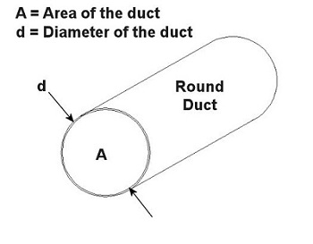
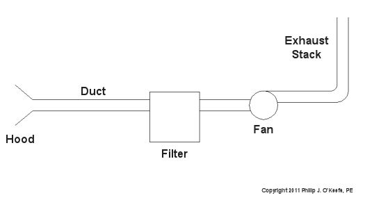
Figure 1 – Local Exhaust Ventilation System With Cyclone Here’s how it works. A local exhaust ventilation system draws in corrupted air by means of a strategically placed hood, and its fan pulls the captured air and dust mixture through ductwork and into the cyclone. The cyclone is shaped like a cone standing upright on its small end. A cutaway view is shown in Figure 2.
Figure 2 – Cutaway View of a Cyclone When a quickly-moving air and dust mixture gets drawn into the cyclone by the fan, the mixture is forced to spiral down into the cone by the shape of the inlet passage. Because dust particles are heavier than air molecules, they tend to separate due to centrifugal force. The heavier dust particles are sent crashing into the sloping sides of the cone. They then slide down to the bottom of the cone, where they will eventually fall through the bottom and into a waiting trash bin. The lighter air tends to stay in the center of the cyclone and is eventually drawn out by the fan through the outlet passage. Unfortunately, cyclones are not 100% efficient when it comes to removing dust from the air. Their efficiency depends on many factors, including the shape of the cyclone, the speed of the flow going through it, and the weight of the dust particles. In any case, there’s always going to be some dust that will escape along with the air that’s being exhausted to the building’s exterior through the exhaust stack. If necessary, this air can be cleaned further before being released into the atmosphere by the use of additional filtration located within the ductwork between the cyclone and the fan. That wraps up our discussion on dust removal through mechanical filtration. Next time we’ll look at systems capable of removing chemical vapors. _____________________________________________ |


Centrifugal Pumps
Sunday, May 16th, 2010|
Last week we focused on various types of positive displacement pumps. Today we’ll take a look at centrifugal pumps. See Figure 1.
Figure 1 – A Centrifugal Pump Just like the positive displacement pumps we talked about last week, centrifugal pumps have rotating parts as well, but that’s where their similarities end. Unlike positive displacement pumps that take “bites” out of liquid before trapping it between moving parts, centrifugal pumps rely on kinetic energy to move liquid in a continuous stream. Kinetic energy is the energy of motion, and in the case of the centrifugal pump kinetic energy is developed by rotating parts within the pump and transferred to the liquid contained within the pump. In other words, the liquid is moved through the pump by means of centrifugal force. To illustrate this concept, we can tie a rope to the handle of a bucket that has a small hole punched in the bottom. Now, you know what will happen if you fill the bucket with water… There’s a hole in the bucket, Dear Liza, Dear Liza… That’s right, the water will just dribble out of the hole, thanks to gravity. But before we fix the hole as Liza suggests, let’s do an experiment. Pick up the rope and spin the bucket around as fast as you can in a circle. You’ll notice that this rapid spinning creates centrifugal force, resulting in a rather powerful stream of water shooting from the hole. The faster you spin the bucket, the stronger the stream. When it comes to centrifugal pumps, the idea is basically the same. The objective is to forcefully spin water around in a circle, thus ejecting it from the pump. This is accomplished with a rotating part called an impeller. See Figure 2.
Figure 2 – Cutaway View of a Centrifugal Pump
In our illustration the impeller is attached to a shaft that’s powered by some source of mechanical energy, such as an electric motor. The water enters the pump at the center of the rotating impeller, referred to as the “eye.” The water then slides over the face of the impeller, moving from the center to its edge due to the action of centrifugal force. That force pushes it off the impeller and into the pump housing. You’ll note that the housing has a special shape, called a “volute.” This volute looks a lot like a spiraled snail shell. The shape of the volute helps direct the water coming off the impeller into an opening in the side of the pump where it is discharged. The faster the pump impeller rotates, the more kinetic energy the water picks up from the impeller. This ends our discussion on pumps. Next time, we’ll move on to a new topic of discussion, braking systems. _____________________________________________ |


Vibration Analysis in Mechanical Engineering, Part II
Sunday, March 14th, 2010|
Last week we began a new article on vibration analysis. This week we’ll continue by looking at how to solve a vibration analysis problem. Analysis of vibration in machine designs typically involves advanced knowledge of kinetics and higher level mathematics like calculus. For this discussion, let’s consider a relatively simple balancing problem for a rotating system of masses. Suppose you have a ball with 10kg of mass on the end of a stick. If you’ll recall from our discussion about kinetics, mass is the weight of an object divided by the acceleration of gravity. For this problem, let’s say that only the ball has mass and not the stick. Although this may seem nonsensical, it is necessary in order not to complicate our analysis well beyond the basic discussion we are having here. Getting back to our ball and stick combo, the other end of the stick is attached to a rotating shaft, and the center of the ball is 0.5 meters (m) away from the center of the shaft. This rotating system is shown in Figure 1. Figure 1 – A Rotating System With One 10kg Ball
When the shaft rotates at 60 revolutions per minute (RPM), the ball moves in a circle around the shaft via the stick as shown in Figure 2. The centrifugal force created by the circular motion of the ball always points at a 90 degree angle to the ball’s path of movement. The net result is an effect similar to that felt when you drive quickly around a sharp right-hand curve and you feel as though you are being pushed to one side.
Figure 2 – Side View of the Rotating System in Figure 1
Getting back to Figure 2, since the centrifugal force is at a 90 degree angle to its movement, it keeps changing direction. When the ball is at the top of its movement, the force points straight up as shown in (a). When the ball is horizontal right, the force points right as shown in (b). When the ball is at the bottom of its movement, the force points down as shown in (c). When the ball is horizontal left, the force points left as shown in (d). This change in the direction of the centrifugal force pulls the rotating system up, to the right, down, and to the left as the shaft rotates, causing vibration in the whole system. The mechanics of this vibration are very similar to the unbalanced load in the washing machine during spin cycle that we talked about last week. To answer this question, let’s apply the formula for centrifugal force on a ball as it rotates in our system above: F = (Mass) x ((RPM) x (1 min. / 60 sec.))2 x (4 π2) x (Distance From Center of Rotation) Plugging in values, the centrifugal force for the 10kg ball is calculated to be: F10kg = (10 kg) x ((60 RPM) x (1 min. / 60 sec.))2 x (4 π2) x (0.5 m) = 197.39 kg m/sec2 = 197.39 Newtons In case you’re wondering, scientists got tired of talking about the metric units of force as “kg m/sec2,” so they decided to rename these units in honor of the great Sir Isaac Newton. In order for the vibration in our example to go away, the centrifugal force for the 10kg ball must equal the centrifugal force of the 6kg ball. Knowing this, we can work backwards to calculate the distance from the center of rotation for the 6kg ball. This distance will be key to balancing the system out because it acts to compensate for the unequal masses of the balls. F6kg = 197.39 kg m/sec2 = (6 kg) x ((60 RPM) x (1 min. / 60 sec.))2 x (4 π2) x (Distance From Center of Rotation6kg) And the distance from the center of rotation becomes: Distance From Center of Rotation6kg = 197.39 kg m/sec2 /[(6 kg) x ((60 RPM) x (1 min. / 60 sec.))2 x (4 π2)] = 0.83 meters This tells us that we’d have to cut our stick so that the center of the 6kg ball is 0.83 meters from the center of the shaft in order to compensate for the vibration caused by the rotating 10kg ball. See Figure 3.
Figure 3 – A Rotating System With One 10kg Ball and One 6kg Ball This concludes our basic look at vibration analysis. Next week we’ll get into the last installment of our mechanical engineering series to see how everything we’ve learned throughout this series ties together in machine design. _________________________________________________________________ |


Vibration Analysis in Mechanical Engineering, Part I
Sunday, March 7th, 2010|
Last week we wrapped up our discussion on heat transfer. This week we’ll turn to a discussion on vibration analysis. Vibration occurs when there is physical movement of a machine part when compared to a point of reference. This physical movement can manifest in a straight line, a circle, or any way imaginable in three dimensions. The point of reference can be a guideway for a sliding part or a shaft for a rotating part. As discussed in kinetics, machine parts have mass, and when mass moves it contains kinetic energy, so it makes sense that when a part moves within a machine, the energy created can result in forces that act upon the machine as a whole. The net result is machine vibration which occurs in “sympathy” with the movement of the original mechanical part under discussion. Let’s talk about examples of vibration caused by straight line and circular motion. And what figure conjures up a better image of up-and-down straight line vibration then a jackhammer, as shown in Figure 1. This tool has a chisel which is attached to an air piston that moves up and down in a straight line, and the chisel and piston each have mass. It is the rapid up and down movement of the total mass of the device that results in concrete-breaking force. Unfortunately, those forces also vibrate back up the jackhammers shaft into the hands, arms and body of the construction worker operating it.
Figure 1 – A Jackhammer
An example of vibration caused by circular movement can be found in your washing machine. Ever notice what happens when you throw one heavy object, say a throw rug, into it, and it begins the spin cycle? That “THUMP-THUMP-THUMP” sound that just won’t quit is due to the rug, now wet and congealed into a single heavy lump to one side of the agitator. It continues to spin about the center of the agitator, creating an unbalanced outward centrifugal force that keeps changing direction around its central pivot point, the agitator. This force makes the washing machine want to rock from side to side and front to back. Now imagine this situation taking place inside your washer day after day, hour after hour, every time you put a load to wash. How long do you think your washer would last under this usage? As this example illustrates, vibrations must be considered in machine design because if they are severe enough, they can cause machine parts to prematurely wear and fail. Speaking of wear and failure, you might have discovered how the tires on your car wore out prematurely and a mechanic said this happened because your shock absorbers or struts are bad. Shock absorbers and struts help to safely control, or “dampen,” vibrations in the suspension system that result when your car’s wheels roll down the highway. Without proper damping, the vibration forces can cause your tire to literally bounce down the road and grind on the pavement with each landing. Oh, yes, if the vibration is strong enough, you can even lose control of your car and end up in a crash. Unfortunately, strong vibrations do not only affect machinery, but the people that come into contact with them, often causing physical discomfort and injury. Ever heard of “white finger syndrome,” otherwise known as Raynaud’s syndrome? This painful condition, which results when vibrations impair blood flow to the fingers, causes them to tingle, feel numb, and then turn white. The longer a person uses a vibrating tool, and the faster the tool vibrates, the greater the risk. Well that’s our initial plunge into the world of vibrations. Now that we know the basics of what vibrations are and what they can do, next time we can explore how to resolve a straightforward vibration problem which often presents itself in rotating mechanisms. _________________________________________________________________ |


