| We’ve all popped a circuit breaker sometime in our lives, often the result of making too heavy of an electrical demand in a single area of the house to which that circuit is dedicated. Like when you’re making dinner and operating the microwave, toaster, mixer, blender, food processor, and television simultaneously. The demand for current on a single circuit can be taxed to the max, causing it to pop the circuit breaker and requiring that trip to the electrical box to flip the switch back on.
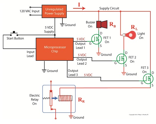
Last time we began our discussion on unregulated power supplies and how they’re affected by power demands within their circuits. Our schematic shows there are two basic aspects to the circuit, namely, its direct current source, or VDC, and its internal resistance, RInternal. Now let’s connect the power supply output terminals to an external supply circuit through which electrical current will be provided to peripheral devices, much like all the kitchen gadgets mentioned above.
Figure 1
The external supply circuit shown in Figure 1 contains various electronic components, including electric relays, lights, and buzzers, and each of these has its own internal resistance. Combined, their total resistance is RTotal, as shown in our schematic. Current, notated as I, circulates through the power supply, through the external supply circuit, and then returns back to the power supply. The current circulates because the voltage, VDC, pushes it through the circuit like pressure from a pump causes water to flow through a pipe. RTotal and I can change, that is, increase or decrease, depending on how many components the microprocessor has turned on or off within the external supply circuit at any given time. When RTotal increases, electrical current, I, decreases. When RTotal decreases, electrical current I increases. Next time we’ll continue our discussion on Ohm’s Law, introduced last week, to show how the static effect of RInternal interacts with the changing resistance present in RTotal to adversely affect an unregulated power supply’s output voltage. ____________________________________________ |
Posts Tagged ‘circuit breaker’
Transistors – Voltage Regulation Part IV
Sunday, August 12th, 2012
Industrial Control Basics – Disconnect Switches
Sunday, March 25th, 2012| Last week our kitchen ceiling fan and light combo decided to stop working. We don’t like eating in the dark, so I was compelled to do some immediate troubleshooting. As an engineer with training in the workings of electricity I have a great respect for it. I’m well aware of potential hazards, and I took a necessary precaution before taking things apart and disconnecting wires. I made the long haul down the stairs to the basement, opened the circuit breaker in the electrical panel, and disabled the flow of electricity to the kitchen. My fears of potential electrocution having been eliminated, my only remaining fear was of tumbling off the ladder while servicing the fan.
Just as I took the precaution to disconnect the power supply before performing electrical maintenance in my home, workers in industrial settings must do the same, and a chief player in those scenarios is the motor overload relay discussed last week. It automatically shuts down electric motors when they become overheated. Let’s revisit that example now.
Figure 1
Our diagram in Figure 1 shows electric current flowing through the circuit by way of the red path. Even if this line were shut down, current would continue to flow along the path, because there is no means to disconnect the entire control system from the hot and neutral lines supplying power to it, that is, it is missing disconnect switches. Electric current will continue to pose a threat to workers were they to attempt a repair to the system. Now let’s see how we can eliminate potential hazards on the line.
Figure 2
In Figure 2 there is an obvious absence of the color red, indicating the lack of current within the system. We accomplished this with the addition of disconnect switches capable of isolating the motor control circuitry, thereby cutting off the hot and neutral lines of the electrical power supply and along with it the unencumbered flow of electricity. These switches are basically the same as those seen in earlier diagrams in our series on industrial controls, the difference here is that the two switches are tied together by an insulated mechanical link. This link causes them to open and close at the same time. The switches are opened and closed manually via a handle. When the disconnect switches are both open electricity can’t flow and nothing can operate. Under these conditions there is no risk of a worker coming along and accidentally starting the conveyor motor. To add yet another level of safety, disconnect switches are often tagged and locked once de-energized. This prevents workers from mistakenly closing them and starting the conveyor while maintenance is being performed. Brightly colored tags alert everyone that maintenance is taking place and the switches must not be closed. The lock that performs this safety function is actually a padlock. It’s inserted through a hole in the switch handle, making it impossible for anyone to flip the switch. Tags and locks are usually placed on switches by maintenance personnel before repairs begin and are removed when work is completed. Now let’s see how our example control system looks in ladder diagram format.
Figure 3
Figure 3 shows a ladder diagram that includes disconnect switches, an emergency stop button, and the motor overload relay contacts. The insulated mechanical link between the two switches is represented by a dashed line. Oddly enough, engineering convention has it that the motor overload relay heater is typically not shown in a ladder diagram, therefore it is not represented here. This wraps up our series on industrial control. Next time we’ll begin a discussion on mechanical clutches and how they’re used to transmit power from gasoline engines to tools like chainsaws and grass trimmers. ____________________________________________
|


Industrial Ventilation
Sunday, March 27th, 2011| On a hot, sticky day, what price would you pay for a cool breeze? Imagine for a moment that it’s 90 degrees in the shade and humidity is 85%. There are few human beings that wouldn’t consider this uncomfortable weather, although I have some die hard neighbors who rarely close their windows during the summer to engage the air conditioning, a rather recent modern convenience. My mom told me stories of how it was common in the 1940s for entire Chicago neighborhoods to head to Lake Michigan, spread a blanket, and sleep on the beach to keep cool on the hottest nights. As for myself, I remember being really happy when Dad broke down and finally purchased a window air unit. It was as big as a small refrigerator and took two men to lift. It was loud and drew so much power it frequently “blew the fuse.” It was so much nicer when central air conditioning came along a few years later and we could finally retire that old clunker.
Ultimately, it’s ventilation that makes air conditioning work, the principle here being a continuous circulation of air, exchanging hot for cooled. If you’ll remember, hot air gives up its heat to coils containing coolant, and the newly cooled air is released back into the room. In addition to cooling, another major function of ventilation is to remove odors and refresh the air. Everyone likes a fresh smelling home, but even more importantly, proper ventilation reduces the concentration of contaminants in the air, things which tend to make us sick, like mold. That’s why many states’ building codes require whole house air ventilation systems to be installed in new homes. In industrial settings ventilation performs the same functions, but it’s necessary for other reasons as well. Industrial facilities often house processes that create airborne toxins and other contaminants. These byproducts of manufacturing can be dangerous if allowed to collect unchecked within the confines of a building. Air containing certain concentrations of contaminants, such as vapors emitted by paints and solvents, can ignite, resulting in fire or explosion. For safety of both workers and equipment, fresh air must displace air contaminated with fumes and dust. There are three types of ventilation that can be found in industrial facilities. These include indoor air quality ventilation, dilution ventilation, and local exhaust ventilation. Indoor air quality ventilation provides freshly heated or cooled air to buildings as part of the normal heating, ventilating and air conditioning system, much like we have in our own homes. Dilution ventilation gets its name from the fact that it dilutes contaminated air by displacement, the blowing in of clean air and exhausting of dirty. The last type of ventilation, local exhaust ventilation, captures contaminated emissions at or near the source and exhausts them directly outside. Depending on the type of industrial application one, two, or all three of these ventilation types may be employed to keep air quality safe. Next week we’ll discuss dilution ventilation in detail, followed by local exhaust ventilation, and we’ll gain a better understanding of how they are used to protect worker health and safeguard property. _____________________________________________ |
Arc Flash Dangers
Sunday, September 13th, 2009|
Imagine being hit by a bolt of lightning. Like lightning, an arc flash can unexpectedly release tremendous amounts of energy, resulting in serious injuries and even death. An arc flash is the result of a short circuit or electrical fault in energized equipment. Current flows through the air and creates an electrical arc, very much like the phenomenon of lightning. But unlike lightning, arc flash dangers are present in a myriad of circumstances that do not require storm conditions to manifest. Over 80% of electrically related injuries involve some type of arc flash. They can be caused by a wide variety of factors, including: equipment malfunctions, inadequate safety procedures, carelessness, lack of training, dropped tools, etc. The amount of energy released by the electrical arc depends on the amount of electrical current flowing through the arc and how long the current will flow before it is interrupted by a circuit breaker or fuse. The radiation released in an arc flash can be so intense and so rapid that it can instantly burn skin and ignite clothing. Temperatures at the electrical arc can rapidly climb to tens of thousands of degrees. At temps this extreme metal becomes liquid, then vaporizes, and the air surrounding the arc becomes superheated to approximately 30,000°F. The superheated air and metal vapor together expand with explosive force. This creates a dangerous and potentially lethal pressure wave of hot gas, molten metal droplets, and solid metal shards that can create burns and shrapnel wounds.
The Occupational Safety and Health Administration (OSHA) requires employers to assess the workplace for arc flash hazards that are present or that are likely to be present. Assessment is done using standards developed by the National Fire Protection Association (NFPA) and the Institute of Electrical and Electronics Engineers (IEEE) to specifically address arc flash hazards. If hazards are identified, employers must mitigate risks by adhering to a six point compliance plan such as the following: 1. Implement a worker safety program with defined responsibilities. 2. Perform engineering studies that include calculations to determine the degree of arc flash hazards. These studies also must be updated when any changes to the electrical system are made by the employer or the electric utility. 3. Provide workers with the correct personal protective equipment (PPE) based on the study results. These PPE must then be maintained on site to protect workers. 4. Provide worker training on the hazards of arc flash. This training must be documented and workers must demonstrate proficiency through testing. Worker training must also be updated whenever any changes occur to the electrical system. 5. Provide appropriate tools for safe working. 6. Place conspicuous warning labels on equipment to warn workers about potential arc flash hazards. OSHA, like other government agencies, expects employers to keep up with regulations and take the necessary steps to remain compliant. For example, OSHA won’t send notices out to employers to inform them that they must implement an arc flash program in their plant. It’s up to the employers to know that and institute the necessary precautions on their own. It must also be noted that OSHA doesn’t walk employers through the steps of setting up an effective worker safety program. This means that workers can be exposed to arc flash hazards simply because their employer is ignorant of regulatory requirements and is operating based on misconceptions. Some workers are unfortunate enough to work for employers that don’t take potential dangers like arc flash seriously enough to implement an effective safety program. When their wakeup call comes, it’s often too late. _________________________________________________________________ Do you want to know more about implementing an effective Arc Flash Program in your facility? Phil O’Keefe developed and presents a 90-minute webinar entitled: “Arc Flash Program Fundamentals.” Contact him for more information about conducting this webinar for your organization. |


