Posts Tagged ‘circuitry’
Sunday, September 9th, 2012
| Back in the early 1970s my dad, a notorious tightwad, coughed up several hundred dollars to buy his first portable color television. That was a small fortune back then. The TV was massive, standing at 24 inches wide, 18 inches high, and 24 inches deep, and weighing in at about 50 pounds. I think the only thing that made this behemoth “portable” was the fact that it had a carrying handle on top.
A major reason for our old TV being so big and clunky was of course due to limitations in technology of the time. Many large, heavy, and expensive electronic components were needed to make it work, requiring a lot of space for the circuitry. By comparison, modern flat screen televisions and other electronic devices are small and compact because advances in technology enable them to work with far fewer electronic components. These components are also smaller, lighter, and cheaper.
Last time we looked at the components of a simple unregulated power supply to see how it converts 120 volts alternating current (VAC) to 12 volts direct current (VDC). We discovered that the output voltage of the supply is totally dependent on the design of the transformer, because the transformer in our example can only produce one voltage, 12 VDC. This of course limits the supply’s usefulness in that it is unable to power multiple electronic devices requiring two or more voltages, such as we’ll be discussing a bit further down.
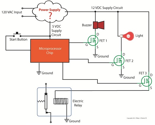
Now let’s illustrate this power supply limitation by revisiting our microprocessor control circuit example which we introduced in a previous article in this series on transistors.

Figure 1
In Figure 1 we have to decide what kind of power to supply to the circuit, but we have a problem. Sure, the unregulated power supply that we just discussed is up to the task of providing the 12 VDC needed to supply power for the buzzer, light, and electric relay. But let’s not forget about powering the microprocessor chip. It needs only 5 VDC to operate and will get damaged and malfunction on the higher 12 VDC the current power supply provides. Our power supply just isn’t equipped to provide the two voltages required by the circuit.
We could try and get around this problem by adding a second unregulated power supply with a transformer designed to convert 120 VAC to 5 VAC. But, reminiscent of the circuitry in my dad’s clunky old portable color TV, the second power supply would require substantially more space in order to accommodate an additional transformer, diode bridge, and capacitor. Another thing to consider is that transformers aren’t cheap, and they tend to have some heft to them due to their iron cores, so more cost and weight would be added to the circuit as well. For these reasons the use of a second power supply is a poor option.
Next time we’ll look at how adding a transistor voltage regulator circuit to the supply results in cost, size, and weight savings. It also results in a more flexible and dependable output voltage.
____________________________________________ |
Tags: 12 VDC, 120 VAC, 5 VDC, buzzer, capacitor, circuit, circuitry, damage, digital logic chip, diode bridge, electric relay, electronic component, electronic device, electronics, engineering expert witness, FET, field effect transformer, forensic engineer, light, malfunction, microprocessor chip, microprocessor control, multiple voltage, power supply, television, transformer, transistor, unregulated power supply, voltage regulator, volts alternating current, volts direct current
Posted in Engineering and Science, Expert Witness, Forensic Engineering, Innovation and Intellectual Property, Personal Injury, Product Liability | Comments Off on Transistors – Voltage Regulation Part VIII
Sunday, March 25th, 2012
| Last week our kitchen ceiling fan and light combo decided to stop working. We don’t like eating in the dark, so I was compelled to do some immediate troubleshooting. As an engineer with training in the workings of electricity I have a great respect for it. I’m well aware of potential hazards, and I took a necessary precaution before taking things apart and disconnecting wires. I made the long haul down the stairs to the basement, opened the circuit breaker in the electrical panel, and disabled the flow of electricity to the kitchen. My fears of potential electrocution having been eliminated, my only remaining fear was of tumbling off the ladder while servicing the fan.
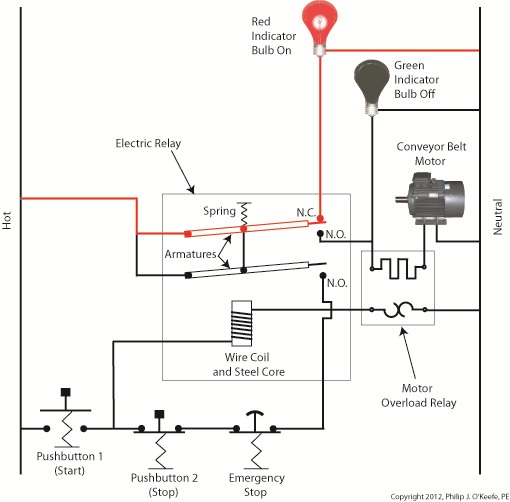
Just as I took the precaution to disconnect the power supply before performing electrical maintenance in my home, workers in industrial settings must do the same, and a chief player in those scenarios is the motor overload relay discussed last week. It automatically shuts down electric motors when they become overheated. Let’s revisit that example now.

Figure 1
Our diagram in Figure 1 shows electric current flowing through the circuit by way of the red path. Even if this line were shut down, current would continue to flow along the path, because there is no means to disconnect the entire control system from the hot and neutral lines supplying power to it, that is, it is missing disconnect switches. Electric current will continue to pose a threat to workers were they to attempt a repair to the system. Now let’s see how we can eliminate potential hazards on the line.

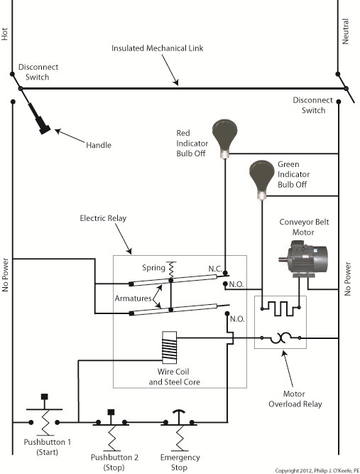
Figure 2
In Figure 2 there is an obvious absence of the color red, indicating the lack of current within the system. We accomplished this with the addition of disconnect switches capable of isolating the motor control circuitry, thereby cutting off the hot and neutral lines of the electrical power supply and along with it the unencumbered flow of electricity.
These switches are basically the same as those seen in earlier diagrams in our series on industrial controls, the difference here is that the two switches are tied together by an insulated mechanical link. This link causes them to open and close at the same time. The switches are opened and closed manually via a handle. When the disconnect switches are both open electricity can’t flow and nothing can operate. Under these conditions there is no risk of a worker coming along and accidentally starting the conveyor motor.
To add yet another level of safety, disconnect switches are often tagged and locked once de-energized. This prevents workers from mistakenly closing them and starting the conveyor while maintenance is being performed. Brightly colored tags alert everyone that maintenance is taking place and the switches must not be closed. The lock that performs this safety function is actually a padlock. It’s inserted through a hole in the switch handle, making it impossible for anyone to flip the switch. Tags and locks are usually placed on switches by maintenance personnel before repairs begin and are removed when work is completed.
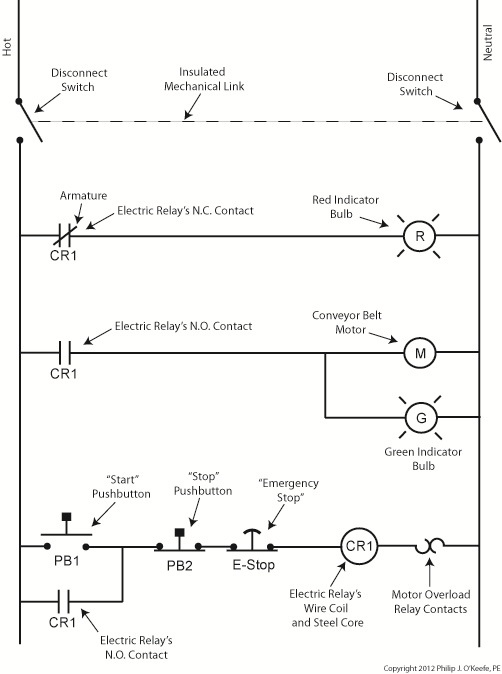
Now let’s see how our example control system looks in ladder diagram format.

Figure 3
Figure 3 shows a ladder diagram that includes disconnect switches, an emergency stop button, and the motor overload relay contacts. The insulated mechanical link between the two switches is represented by a dashed line. Oddly enough, engineering convention has it that the motor overload relay heater is typically not shown in a ladder diagram, therefore it is not represented here.
This wraps up our series on industrial control. Next time we’ll begin a discussion on mechanical clutches and how they’re used to transmit power from gasoline engines to tools like chainsaws and grass trimmers.
____________________________________________
|
Tags: chainsaw, circuit breaker, circuitry, clutch, control panel, conveyor belt, current flow, death, disconnect switch, electric motor, electric relay, electrical maintenance, electrical panel, electricity, electrocution, emergency stop, engineering expert witness, forensic engineer, hot, indicator bulbs, industrial control system, injury, lawn trimmer, lock, lockout tag out, maintenance worker, motor overheated, neutral, overload relay, overload relay heater, potential hazards, power supply, pushbutton, safety, safety hazard, tag, troubleshooting, wires
Posted in Engineering and Science, Expert Witness, Forensic Engineering, Innovation and Intellectual Property, Personal Injury, Product Liability, Professional Malpractice | Comments Off on Industrial Control Basics – Disconnect Switches


