| When something is said to be the “heart of the operation,” one usually imagines that it is integral to whatever is being discussed, and it is probably centrally located. The human heart fits this description well. This amazing organ, centrally located within your chest cavity, moves blood, nutrients, oxygen, and carbon dioxide through your body with amazing efficiency. During a twenty four hour period it can pump as much as 2,000 gallons of blood through 6,000 miles of arteries, veins, and capillaries.
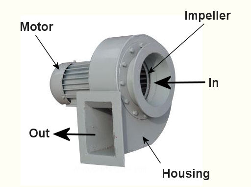
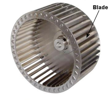
At the heart of a local exhaust ventilation system is its fan. Like the human heart, it is a model of efficiency. It first creates a vacuum in the intake hood, which is strategically located at a pollution source, pulling in contaminated air and leading it through ductwork. Sometimes the fan leads the air to a filter or other air cleaning equipment, but eventually the dirty air is exhausted through a stack leading outdoors. There are two main types of fan, axial and centrifugal. You’re probably most familiar with the axial type, because they’re the type commonly used in tabletop, box, and oscillating fans in your home. These have blades that look like a propeller on an airplane, and they work by drawing air straight through the fan. As helpful as they are within a personal setting, axial fans are not typically used in local exhaust ventilation systems because the electric motor that drives the blades is in the path of airflow. This setup can create a problem if the air flowing over the motor contains dust and flammable vapor. Dust can cause the motor to get dirty and overheat. Flammable vapor can ignite if the motor wiring fails and creates an electrical arc. Because of the technical difficulties presented by an axial type fan, centrifugal fans are what are most often used in industrial settings. One such fan is shown in Figure 1. Figure 1 – Centrifugal Fan The blades of a centrifugal fan are fully enclosed in air tight housing. This housing keeps any dust or fumes from leaking out into the building. The electric motor that drives the fan can be safely located outside of this housing, where it is dust-free and there are no flammable vapors. If you look inside the housing you will see that the moving part, known as the impeller, resembles a squirrel cage. See Figure 2. Figure 2 – Centrifugal Fan Impeller This impeller is made up of many blades, set up within a wheel configuration. When an electric motor causes the wheel to rotate, air is made to move off the blades and out of the impeller due to centrifugal force. This air is sent crashing into the fan housing, shown in Figure 1, which is curved like a spiral to direct the air into an outlet duct which is connected to ductwork that leads to the exhaust stack. As air leaves the impeller, more air rushes into its center from the inlet duct to occupy the empty space that’s been created. Hence, as long as the motor keeps spinning the impeller, air will flow through the fan. In order for all this to work effectively, the centrifugal fan must be the right size, one that is capable of providing enough suction to capture contaminated air at the hood source, then overcoming the resistance to air flow that is presented by ductwork, filters, and other air cleaning devices. Because air resistance factors such as these impede the fan’s ability to move air through the system, the fan must be of sufficient strength make up for these factors. To size up the right centrifugal fan for the job, engineers must calculate the resistance to airflow that is expected to be encountered, and to do this they use data supplied by manufacturers of component parts, as well as tabulated data that is readily available in engineering handbooks. Just as a lawn mower engine won’t provide sufficient energy to power a car, an undersized fan won’t be able to move air through a system which is beyond its capacity limit. Next time, we’ll finish our series on local exhaust ventilations systems by looking at the last component in the system: the exhaust stack. _____________________________________________ |
Posts Tagged ‘ductwork’
Industrial Ventilation – Local Exhaust Ventilation Fans
Sunday, May 22nd, 2011Industrial Ventilation – Local Exhaust Ventilation Filters and Air Cleaners III
Sunday, May 15th, 2011| I was out in the garage today spray painting, a job I would have preferred to have done outdoors, but alas, it was raining. It wasn’t a big job, and I probably didn’t spend more than about an hour doing it, but by the time I was done I was all too aware of how noxious the chemical fumes were that were put out by my aerosol spray can. I had thought that with all the garage doors open and a good cross breeze going through I’d be spared the unpleasant smell. Now imagine this all on a much larger scale, say an industrial setting, where massive spray painters are used all day long.
We’ve been talking for awhile now about filtration, from fabric filters to cyclones, and how they are most effective when integrated into a local exhaust ventilation system. These filtration devices are great for the removal of airborne particles like dust, but they don’t do a good job removing chemical vapors like paint fumes, much in the same way as a dust mask wouldn’t have made my spray painting job any less smelly. This week we’ll focus on filtration capable of addressing the special challenges presented by chemical vapors in the air. Chemical vapor contaminants can be separated from good air trapped in a local exhaust ventilation system by way of an air cleaner in a process known as absorption. In this instance, just like with our smelly goldfish tank, the media can consist of activated carbon, a carbon created by intense heating of substances like bituminous coal, wood, or coconut shell. The heat removes everything except carbon and creates myriads of tiny pores throughout. These pores give activated carbon tremendous surface area, meaning lots of nooks and crannies for chemical molecules to get lodged in. And when I say “lots” of nooks and crannies, I mean it. One pound of granular activated carbon has enough pores to give it a surface area of 125 acres! As the air-vapor mixture passes over the huge surface area, chemical vapors are absorbed by combining chemically with the carbon. Jamb packing surface area into a small space, as activated carbon does, creates a media capable of absorbing vast amounts of chemical molecules for a long time. As effective as this system is, the carbon pores will eventually become saturated with contaminants, and when it does, it is easily addressed. Simply replace the media with fresh carbon. Another means of removing harmful vapors from the air is through the use of an air cleaner employing temperature as its means of filtration. I’ll bet you’re asking how that works, and here’s an example you can relate to. It’s a hot, humid day, and the only thing standing between you and total discomfort is a glass of ice water. As you eagerly lift the glass to your lips, you notice the glass is wet on the outside, so wet that it’s actually dripping. In the stupor caused by your heat exhaustion you may for a moment think that the glass is actually leaking, but you soon realize that the water has accumulated on the outside of the glass because the hot, humid air that is making you so uncomfortable has also come into contact with the cold surface of the glass. When the water vapor in the atmosphere hits the cool of the glass filled with ice, it condenses into droplets. This condensation process stops when the glass temperature equalizes to that of the temperature in the surrounding air. Air cleaners can make use of the same phenomenon to filter contaminants. In their case the contaminated air mixture is cooled to the point where the humidity and chemical vapors present condense together to form a liquid, and the liquid is then drained out for proper disposal. That’s it for our look at filters and air cleaners. To sum things up, remember that there are a variety of factors that have to be considered when selecting filters and air cleaning devices. These include the volume of air flowing through the system, the concentration of contaminants in the air, the chemical and physical properties of the contaminants, the hazards associated with the contaminants, and the emissions standards established by federal, state, and local environmental regulations. Next time we’ll explore the workhorse of a local exhaust ventilation system, its fan. _____________________________________________ |
Industrial Ventilation – Local Exhaust Ventilation Filters and Air Cleaners II
Monday, May 9th, 2011|
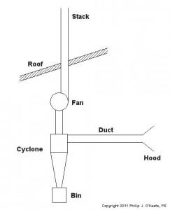
We’ve been talking about mechanical filtration, like the type used by fish tanks. Now we’ll consider another type, the “cyclone.” It’s something which most of us have become very familiar with, thanks to a British bloke and his awesome vacuum that “…won’t lose suction!” His invention makes use of the principles of cyclone technology, and as effective as it is used in vacuums, it’s equally impressive used in local exhaust ventilation system applications. A cyclone that has been incorporated within this type of system is shown in Figure 1. Figure 1 – Local Exhaust Ventilation System With Cyclone Here’s how it works. A local exhaust ventilation system draws in corrupted air by means of a strategically placed hood, and its fan pulls the captured air and dust mixture through ductwork and into the cyclone. The cyclone is shaped like a cone standing upright on its small end. A cutaway view is shown in Figure 2. Figure 2 – Cutaway View of a Cyclone When a quickly-moving air and dust mixture gets drawn into the cyclone by the fan, the mixture is forced to spiral down into the cone by the shape of the inlet passage. Because dust particles are heavier than air molecules, they tend to separate due to centrifugal force. The heavier dust particles are sent crashing into the sloping sides of the cone. They then slide down to the bottom of the cone, where they will eventually fall through the bottom and into a waiting trash bin. The lighter air tends to stay in the center of the cyclone and is eventually drawn out by the fan through the outlet passage. Unfortunately, cyclones are not 100% efficient when it comes to removing dust from the air. Their efficiency depends on many factors, including the shape of the cyclone, the speed of the flow going through it, and the weight of the dust particles. In any case, there’s always going to be some dust that will escape along with the air that’s being exhausted to the building’s exterior through the exhaust stack. If necessary, this air can be cleaned further before being released into the atmosphere by the use of additional filtration located within the ductwork between the cyclone and the fan. That wraps up our discussion on dust removal through mechanical filtration. Next time we’ll look at systems capable of removing chemical vapors. _____________________________________________ |
Industrial Ventilation – Local Exhaust Ventilation Filters and Air Cleaners
Sunday, May 1st, 2011|
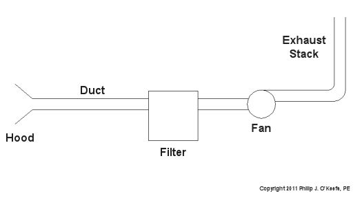
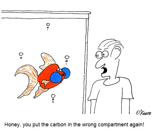
My wife is an aquarist, meaning she keeps aquariums. Three of them. Each contains a different variety of fish housed within its own unique liquid environment. One of these is a 35 gallon tank containing three goldfish. These fish have two unique characteristics that make them especially noteworthy, they are extremely hardy and extremely dirty. Hardly a week can go by between tank changes before the water quality starts to deteriorate, evidenced by cloudy, stinky water. It’s the kind of stink that makes a passerby in the area exclaim, “Who used the bathroom and didn’t turn on the exhaust fan!” Thank goodness for activated carbon. With its proper placement inside the aquarium’s filtration system a cleaner, fresher environment is delivered, both to fish inside the tank and the humans who watch them from outside. Put the carbon in the wrong compartment, however, and the water quality plummets back to its original fetid state within a matter of days. As is true with the proper care of goldfish, it is often necessary within an industrial environment to remove contaminants before the air that contains them is once again dispersed into the general environment. This is where filters and air cleaners come in. They’re generally placed inside the ductwork, somewhere between the hood and fan. Their job is to ensure a good, clean outcome, usually through an external exhaust of some sort. Local exhaust ventilation systems begin with a precisely positioned hood at the source of contamination and end with an exhaust stack located outside the building. Some airborne contaminants being released from the stack are deemed unsafe for the environment, and outdoor air quality standards promulgated by state and federal Environmental Protection Agencies limit their release back into the atmosphere. For this reason the proper use of filtration and air cleaners is crucial. Airborne contaminants are in the form of dusts and vapors. If the issue to be addressed comes in the form of dust, then filters and mechanical separators are commonly used. Filters, like the atmospheric conditions they are meant to address, come in many configurations. They are typically positioned within the local exhaust ventilation system ductwork, as shown in Figure 1 below. Figure 1 – Local Exhaust Ventilation System With Filter The fan draws in air and dust through the strategically positioned hood, located at the source of contamination, then follows a course through ductwork, passing through a filter along the way. The filter contains media with holes tiny enough to allow for air to pass through, but small enough to stop dust particles. The cleaned air is then drawn out of the filter by a fan, which finally exhausts it into an externally positioned stack. Next time we’ll continue our discussion on filtration devices by examining a cyclone. And no, I don’t mean the famous vacuum cleaner, although the methodology is similar. _____________________________________________ |
Industrial Ventilation – Local Exhaust Ventilation Ductwork
Monday, April 25th, 2011| Ever venture into your basement and stare in amazement at the labyrinth of ductwork stemming off from the furnace? Believe it or not, there’s a science behind that spaghetti bowl configuration. Ductwork can either be flexible or rigid, square or round in shape. Its job in a local exhaust ventilation system is to carry airborne contaminants from the originating source, the carefully positioned hood in the workplace, to the exhaust stack where it is vented outside the building. This job isn’t an easy one. Fluids, like air thick with toxins and toxic gases, don’t want to flow very well through ductwork unless you make their path as unimpeded as possible.
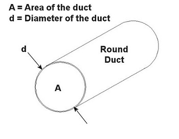
You can think of the air and contaminants flowing through ductwork as if it were like a car moving down a highway. Expressways don’t have sharp 90 degree turns or abrupt changes in width. These would cause a slow down in traffic, unless of course an accident is in the way. Expressways also tend to be rather large thoroughfares. The science behind ductwork follows the same basic principles to work effectively. It will minimize or eliminate sharp turns and it will avoid any abrupt changes in diameter. It will also be as wide in diameter as the environment will accommodate in order to move air volume most effectively. A local exhaust ventilation system’s performance can be greatly hampered and workers exposed to hazards if ductwork leaks. And if the leaks are upstream of the fan and large enough, they can reduce the ability of the local exhaust ventilation system to draw the airborne contaminants into the hood. Air starts getting drawn in through the leaks rather than through the hood. If the leaks are downstream of the fan, the airborne contaminants can re-enter the work area through the leaks rather than going outside through the exhaust stack. Ducts come in an endless variety of diameters, the diameter being part of a simple mathematical equation relating to flow velocity. In the simplest of terms, the flow of air through ductwork is governed by the following equation: Q = V × A where Q is the flow rate of air through the duct in cubic feet per minute (CFM), V is velocity of the air flow in feet per minute, and A is the cross sectional area of the duct in square feet. As an example, suppose you want to design a local exhaust ventilation system with ducts no greater than 5 inches in diameter because of space and clearance limitations. You want to use round ducts for the system because they handle air more efficiently and have no sharp corners where dust can collect. If an industrial hygienist determines that the air is required to flow at a minimum of 800 feet per minute through the duct, what is the airflow rate through the duct? Well, since we are dealing with a round duct, its cross sectional area is that of a circle: A = (π × d2) ÷ 4 where d is the diameter of the inside of the duct as shown in Figure 1 below. Figure 1 – Cross Section of a Round Duct So to use this equation for area, to solve for Q, then we must first convert the duct diameter from inches to feet, which makes our equation look like this: 5 inches ÷ 12 inches per foot = 0.416 feet This gives us a duct cross sectional area of: A = (π × (0.416 feet) 2) ÷ 4 = 0.136 square feet And the air will flow through the duct at this rate: Q = V × A = 800 ft./minute × 0.136 ft.2 = 108.8 CFM This air flow rate is good to know, because it will help the designer to select an appropriate fan for the local exhaust ventilation system. This is because fans are listed in manufacturers’ catalogs according to how many CFM they can handle. Next time, we’ll learn more about the rest of the local exhaust ventilation system, namely, the filter, fan, and exhaust stack. _____________________________________________ |
Industrial Ventilation – Local Exhaust Ventilation Hoods
Sunday, April 17th, 2011| I’m a husband who occasionally does a little vacuuming, at least of the areas I’m responsible for messing up. It’s not one of my favorite activities, and I particularly hate it when I’m in a hurry and I don’t have enough time to move things out of the way. That’s when an accident is prone to happen, and I end up sucking something besides dirt into the hose. The extra work I’ve just created for myself results in my having to open up the vacuum bag and start sifting through the debris. In the end, I sometimes end up making a bigger mess than the one I started out with.
Vacuums are wonderful tools, when used correctly. And when you think about it, the constituent elements of a household canister vacuum cleaner are similar to those of an industrial local exhaust ventilation system. My home vac is comprised of five main elements, all of which most of you are familiar with: a nozzle, hose, filter, a fan located inside the canister to provide suction, and an exhaust hole, also located within the canister, which serves to discharge newly filtered air back into the atmosphere. Industrial usage local exhaust ventilation systems also typically consist of five constituent elements, namely, a hood, ducts, an air cleaning device, a fan, and an exhaust stack. Like my home vacuum its main objective is to suck something in, namely, contaminated air. Let’s take a closer look at each of the parts. The hood is located at the beginning of the local exhaust ventilation system, and like your home vac’s nozzle, it’s positioned in close proximity to the area requiring cleaning. The objective is of course to capture contaminants at the source. Now placement of the hood within the work area is very important. Ultimately it must be far enough away from the source of contamination so as not to interfere with the work that’s being done, yet close enough to prevent contaminants from escaping. Hoods that almost completely enclose the work area provide the best control of contaminants. Trouble is, they can interfere with the work process. That’s where a specific design of hood, known as a “capture exhaust hood” comes in handy. This type of hood is attached to a flexible duct that resembles a super-sized vacuum cleaner hose. This arrangement provides greater flexibility than a huge, all-encompassing hood, and it also allows the hood to be easily positioned anywhere within the workplace as necessary. Again, placement of a capture exhaust hood is critical to its effective operation. Say for instance that a hood is initially positioned a mere two inches from a source of fumes, then someone comes along and bumps it. It ends up being four inches away from the source, and now it will require around three times the amount of air volume through the system to provide the same degree of capture as it did when it was just two inches away. If the ventilation system isn’t strong enough to draw in this extra volume of air, fumes will escape into the work area, rendering our cleanup efforts ineffective. Next time we’ll discuss the second main component in a local exhaust ventilation system, its ductwork. _____________________________________________ |
Industrial Ventilation – Local Exhaust Ventilation
Sunday, April 10th, 2011| My wife often says I’m the worst cook she knows. This doesn’t really bother me too much, because she’s the best cook I know, and she keeps me well fed. But there are times that I have to fend for myself in the kitchen, and this sometimes results in a foul smelling mess plastered all over the stove. Lucky for me we have a nice exhaust hood, and it usually manages to suck out the odor before my wife gets home.
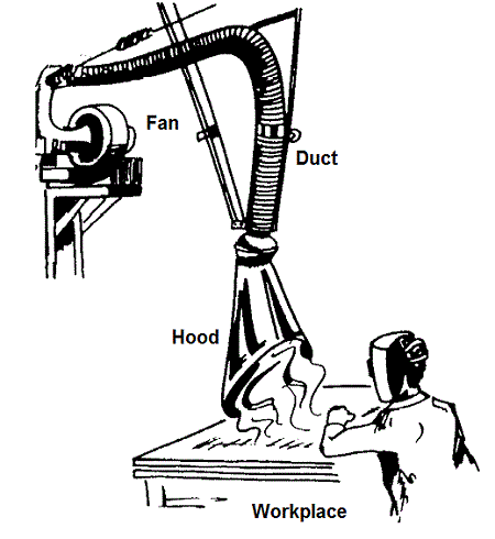
Local exhaust ventilation systems, like the vent over my stove, work much the same way in an industrial setting, albeit on a larger scale. This type of ventilation system gets its name because its action is quite specific, localized to contain exhaust air from a particular area. They’re routinely placed as close as possible to the source of contaminants, and they are able to work quickly to capture and expel chemical vapors, dusts, and fumes, before they spread. This type of ventilation is effective for other reasons, too, because it helps keep down heating and cooling costs. Instead of treating an entire building for ventilation issues, the problem can be nipped in the bud at its source. In many situations, local exhaust ventilation is preferred over dilution ventilation systems for these very reasons. A basic local exhaust ventilation system is comprised of a duct, a fan, and a hood as shown in Figure 1 below. One end of the duct is attached to the intake of the fan. The other end of the duct is attached to the hood. The duct can be rigid or flexible. The hood is positioned in the workplace near the source of contaminants. Figure 1 – Basic Local Exhaust Ventilation System This local exhaust ventilation system operates by much the same principle as the one generally governing the movement of liquids and gases. If you’re a regular reader of this blog, you’ll remember me writing that liquids and gases always flow from areas of higher pressure to those of lower pressure. Well, the air within the room has pressure principles at play as well, and the air within a given work area is at atmospheric pressure. When the fan is introduced into the scenario, a vortex is created within the duct which is less than that of the atmospheric pressure in the room. This difference in pressures causes the room air to flow into the ventilation duct along with its contaminants. The room air and contaminants flow out through the ventilation system, where they are then exhausted outside of the building. But because room air is being drawn into the ventilation system, provisions must be made to supply enough replacement air. Without the proper ratio of air moving in to that moving out, a ventilation system will not work properly. In other words, the suction created by the local ventilation system could cause the pressure in the room to drop below atmospheric pressure. This could cause the higher atmospheric pressure outside the room to bear down on doors, making them difficult to open. Worse yet, contaminants could back up into the room, causing workers to get sick. Now that we’ve covered the basics of local exhaust ventilation, we can move on to its five constituent elements and a discussion of their design. We’ll do that next week. _____________________________________________ |
Industrial Ventilation – Dilution Ventilation
Sunday, April 3rd, 2011| If you’re a fan of the new hit HBO series, Boardwalk Empire, then you know a lot about the effects of Prohibition. But did you know that Prohibition is responsible for the creation of mixed drinks? Until then, people drank their liquor straight. Then along came Prohibition, mob rule, and the desire to keep the booze, including some with questionable origins, flowing. This booze didn’t taste so good, and the addition of a sugary beverage to it, that is, diluting it with soda or juice, made it a lot easier to go down. By the time Prohibition was repealed in 1933, the mixed drink had taken a firm foothold in American society.
Most adults are aware of the fact that liquor, in excess, is toxic to the body. Too much of it, and the liver, which acts as a filtration device, itself becomes toxic. When that happens, poor health will follow. The same principle applies to air within a building. If it becomes thick with toxic fumes or potentially flammable vapors, indoor air quality will suffer. But if you infuse fresh air into the environment, the toxic load is diluted, making the environment habitable and safe. This addition of fresh air is called, appropriately enough, dilution ventilation. Now, the easiest way to create a dilution ventilation system is to open a window. Trouble is there often isn’t enough natural airflow to do much good. But if you step up the effort by introducing a mechanical ventilation system, complete with blowers and ductwork, the need to crack open a window becomes obsolete. By exchanging bad air for good and introducing a continual flow of fresh air, toxicity is diluted and its effects are minimized, much like the bathtub gin of Prohibition was improved by the addition of soda. The chance of fire or explosion is reduced as well. There are however limits to what dilution ventilation can accomplish. If contaminants are highly toxic or extremely flammable, then this type of ventilation system is not going to do much good. This is a situation where extremely high air flows would be required, and this is often impractical both from a cost and comfort standpoint. Imagine having to work inside a wind tunnel? In situations like these a local exhaust ventilation system is better suited to do the job, and we’ll see how those work next week. _____________________________________________ |
