| Last week our kitchen ceiling fan and light combo decided to stop working. We don’t like eating in the dark, so I was compelled to do some immediate troubleshooting. As an engineer with training in the workings of electricity I have a great respect for it. I’m well aware of potential hazards, and I took a necessary precaution before taking things apart and disconnecting wires. I made the long haul down the stairs to the basement, opened the circuit breaker in the electrical panel, and disabled the flow of electricity to the kitchen. My fears of potential electrocution having been eliminated, my only remaining fear was of tumbling off the ladder while servicing the fan.
Just as I took the precaution to disconnect the power supply before performing electrical maintenance in my home, workers in industrial settings must do the same, and a chief player in those scenarios is the motor overload relay discussed last week. It automatically shuts down electric motors when they become overheated. Let’s revisit that example now.
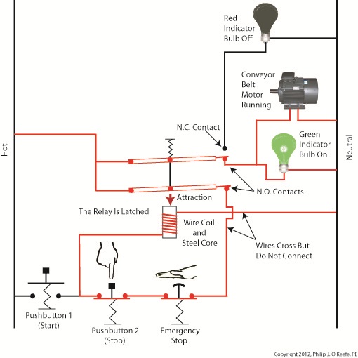
Figure 1
Our diagram in Figure 1 shows electric current flowing through the circuit by way of the red path. Even if this line were shut down, current would continue to flow along the path, because there is no means to disconnect the entire control system from the hot and neutral lines supplying power to it, that is, it is missing disconnect switches. Electric current will continue to pose a threat to workers were they to attempt a repair to the system. Now let’s see how we can eliminate potential hazards on the line.
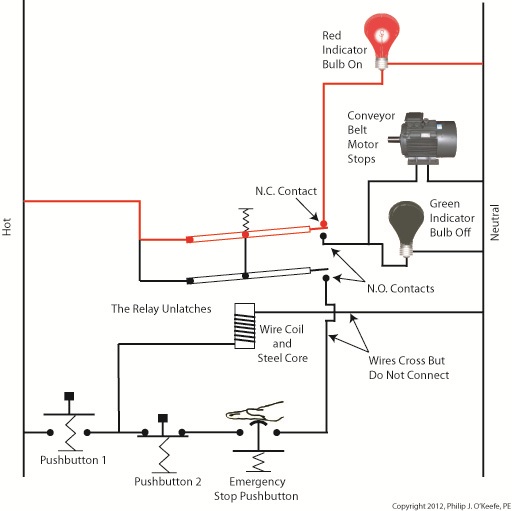
Figure 2
In Figure 2 there is an obvious absence of the color red, indicating the lack of current within the system. We accomplished this with the addition of disconnect switches capable of isolating the motor control circuitry, thereby cutting off the hot and neutral lines of the electrical power supply and along with it the unencumbered flow of electricity. These switches are basically the same as those seen in earlier diagrams in our series on industrial controls, the difference here is that the two switches are tied together by an insulated mechanical link. This link causes them to open and close at the same time. The switches are opened and closed manually via a handle. When the disconnect switches are both open electricity can’t flow and nothing can operate. Under these conditions there is no risk of a worker coming along and accidentally starting the conveyor motor. To add yet another level of safety, disconnect switches are often tagged and locked once de-energized. This prevents workers from mistakenly closing them and starting the conveyor while maintenance is being performed. Brightly colored tags alert everyone that maintenance is taking place and the switches must not be closed. The lock that performs this safety function is actually a padlock. It’s inserted through a hole in the switch handle, making it impossible for anyone to flip the switch. Tags and locks are usually placed on switches by maintenance personnel before repairs begin and are removed when work is completed. Now let’s see how our example control system looks in ladder diagram format.
Figure 3
Figure 3 shows a ladder diagram that includes disconnect switches, an emergency stop button, and the motor overload relay contacts. The insulated mechanical link between the two switches is represented by a dashed line. Oddly enough, engineering convention has it that the motor overload relay heater is typically not shown in a ladder diagram, therefore it is not represented here. This wraps up our series on industrial control. Next time we’ll begin a discussion on mechanical clutches and how they’re used to transmit power from gasoline engines to tools like chainsaws and grass trimmers. ____________________________________________
|
Posts Tagged ‘electricity’


Industrial Control Basics – Motor Overload
Sunday, March 4th, 2012|
Last summer my wife and I did a lot of work in the garden. Many holes were dug, bags of garden soil lifted, and plants planted. It’s a new garden, and my wife has very big plans for it, so needless to say there was a lot of work to be done. On more than one occasion we would end the day moaning about our body aches and how we had overdone it. The next day we would hurt even worse, and we’d end up taking time off to recuperate. Pain is your body’s way of telling you that it needs attention, and you’d better listen to it or you may have an even heavier price to pay down the road. Electric motors can get overworked, just like our bodies. Motors are often placed into situations where they are expected to perform tasks beyond their capability. Sometimes this happens through poor planning, sometimes due to wishful thinking on the user’s part. Motors can sustain damage when stressed in this way, but they don’t have a pain system to tell them to stop. Instead, motors benefit by a specific type of electric relay known as an overload relay. But before we get into how an overload relay works, let’s get a better understanding of how overloads happen. Suppose we’re back in the telephone factory discussed in previous blogs, watching a conveyor belt move phones through the manufacturing process. An electric motor drives the conveyor belt by converting electrical energy into mechanical energy. Everything is moving along normally when all of a sudden a machine malfunctions. Telephones start piling up on a belt, and the pile up gets so bad the belt eventually gets jammed and its motor overloaded. If the electricity flow to the motor isn’t shut down promptly by means of a nearby emergency stop button or an astute operator sitting in central control, then an even bigger problem is in the making, that of a potential fire. When electricity is applied to motors they begin to operate, and their natural tendency is to want to keep operating. They do so by continuously drawing energy from the electric current being supplied to them. The greater the workload demand on the motor, the more current it requires to operate. When motors become overloaded as in the scenario presented above, they continue to draw energy unless forced to a stop. The result is an overabundance of current flowing through the motor and no outlet for its task of converting electrical energy into mechanical energy. And where is all that pent up energy to go? It becomes heat energy trapped inside the motor itself, and this heat can build up to the point where the motor becomes damaged or even bursts into flames. Next time we’ll look at how overload relays work to keep electric motors from overheating, just as our body’s pain sensors protect us from overdoing it.
____________________________________________
|

Industrial Control Basics – Electric Relay Operation
Monday, January 9th, 2012| It’s a dark and stormy night and you’ve come to the proverbial fork in the road. The plot is about to take a twist as you’re forced to make a decision in this either/or scenario. As we’ll see in this article, an electric relay operates in much the same manner, although choices will be made in a forced mechanical environment, not a cerebral one.
When we discussed basic electric relays last week we talked about their resting in a so-called “normal state,” so designated by industrial control parlance. It’s the state in which no electric current is flowing through its wire coil, the coil being one of the major devices within a relay assembly. Using Figure 3 of my previous article as a general reference, in this normal state a relaxed spring keeps the armature touching the N.C. switch contact. While in this state, a continuous conductive path is created for electricity through to the N.C. point. It originates from the wire on the left side, which leads to the armature pivot point, travels through the armature and N.C. contact points, and finally dispenses through the wire at the right leading from the N.C. contact. Now let’s look at an alternate scenario, when current is made to flow through the coil. See Figure l, below.
Figure 1Figure 1 shows the path of electric current as it flows through the wire coil, causing the coil and the steel core to which it’s attached to become magnetized. This magnetization is strong, attracting the steel armature and pulling it towards the steel core, thus overcoming the spring’s tension and its natural tendency to rest in a tension-free state. The magnetic attraction causes the armature to rotate about the pivot point until it comes to rest against the N.O. contact, thus creating an electrical path en route to the N.O. wire, on its way to whatever device it’s meant to energize. As long as current flows through the wire coil, its electromagnetic nature will attract the armature to it and contact will be maintained with the N.O. juncture. When current is made to flow through the wire coil, an air gap is created between the armature and the N.C. contact, and this prevents the flow of electric current through the N.C. contact area. Current is forced to follow the path to the N.O. contact only, effectively cutting off any other choice or fork in the road as to electrical path that may be followed. We can see that the main task of an electric relay is to switch current between two possible paths within a circuit, thereby directing its flow to one or the other. Next time we’ll examine a simple industrial control system and see how an electric relay can be engaged with the help of a pushbutton. ____________________________________________ |

Industrial Control Basics – Manual Control
Monday, December 12th, 2011| You’ve probably heard the saying, “asleep at the switch.” It’s usually associated with some sort of disaster, found later to have been caused by human error. Someone wasn’t paying attention, and something very bad happened. The meltdown of the Soviet nuclear power plant Chernobyl in 1986 comes to mind. You may be surprised to learn that the saying has its origins in the world of industrial controls, or more specifically, manual controls, as we’ll see in this article.
Last week when we opened our discussion on manual controls, we talked about how they work just as their name implies, that is, someone must manually press a button or throw a switch in order to initiate a factory operation. In other words, a manual control requires human intervention to initiate an action, such as pushing the start button. The machine will then continue to run until a person hits the stop button. Let’s go now on a virtual field trip into a telephone factory to see how a basic manual control system works. It has a conveyor belt operated by an electric motor, and this motor is connected by wires and a power switch to a 120 volt power source of alternating current. Figure 1 illustrates what we mean. It shows that when the power switch is in the open position, a physical air gap exists within the electrical circuit. This prevents electricity from flowing through the wire because electricity can’t jump over gaps.
Figure 1 – Open Power Switch Enter a human into the scenario, someone who grabs the power switch handle and manually closes it, eliminating the air gap. See Figure 2.
Figure 2 – Closed Power Switch When the power switch is closed, a metal conductor bridges the gap, causing electricity to flow through the metal conductor to the electric motor in the circuit. This brings life to the conveyor belt. As long as the power switch remains closed, the conveyor belt will continue to operate. That’s it, that’s a basic manual control system. It’s simple to operate, but it does have one major flaw. It requires constant monitoring by a human. Aside from opening and closing a power switch, humans are required to monitor operations, in case something goes wrong. The operator watching over an industrial machine performs the same function as the pilot on a plane, that is, to start-stop operations, and to intervene in case of an emergency. Computers fly modern jets. Pilots serve as trouble shooters when the unanticipated disaster situation occurs, because computers can’t yet creatively problem solve. Next time we’ll introduce the element of an automatic control system, which will virtually eliminate the need for human intervention and with it human error. ____________________________________________ |


Food Manufacturing Challenges – Cleanliness
Monday, October 3rd, 2011| My wife and I have an agreement concerning the kitchen. She cooks, I clean. Plates and utensils are easy enough to deal with, especially when you have a dishwasher. Pots and pans are a little more challenging. But what I hate the most are the food processors, mixers, blenders, slicers and dicers. They’re designed to make food preparation easier and less time consuming, but they sure don’t make the clean up any easier! Quite frankly, I suspect the time involved to clean them exceeds the time saved in food preparation.
Food processors on a larger scale are also used to manufacture many food products in manufacturing facilities, and being larger and more complicated overall, they’re even more difficult to clean. For example, I once designed a production line incorporating a dough mixer for one of the largest wholesale bakery product suppliers in the United States. A small elevator was required to lift vast amounts of ingredients into a mixing bowl the size of a compact car. Its mixing arms were so heavy, two people were required to lift them into position. It was also my task to ensure that the equipment as designed was capable of being thoroughly cleaned in a timely and cost effective manner. Food processing machinery must be designed so that all areas coming into contact with ingredients can be readily accessed for cleaning. And since most of the equipment you are dealing with in this setting is far too cumbersome to be portable, the majority of the cleaning must be cleaned in place, known in the industry as CIP. To facilitate CIP, commercial machinery is designed with hatches and special covers that allow workers to get inside with their cleaning equipment. Small, portable parts of the machine, such as pipes, cutting blades, forming mechanisms, and extrusion dies, are often made to be removable so that they can be carried over to an industrial sized sink for cleaning out of place, or COP. These potable machine components are typically removable for COP without the use of any tools and are fitted with flip latches, spring clips, and thumb screws to facilitate the process. Everything in a food manufacturing facility, from production machinery to conveyor belts, is typically cleaned with hot, pressurized water. The water is ejected from the nozzle end of a hose hooked up to a specially designed valve that mixes steam and cold water. The result is scalding hot pressurized water that easily dislodges food residues. Bacteria doesn’t stand a chance against this barrage. The water, which is maintained at about 180°F, quickly sterilizes everything it makes contact with. It also provides a chemical-free clean that won’t leave behind residues. Once dislodged, debris is flushed out through strategically placed openings in the machine which then empty into nearby floor drains. As a consequence of the frequent cleanings commercial food preparation machinery requires, their parts must be able to withstand frequent exposure to high pressure water streams. Parts are typically constructed of ultra high molecular weight (UHMW) food-grade plastics and metal alloys such as stainless steels, capable of withstanding the corrosive effects of water. And since water and electricity make a dangerous combination, gaskets and seals on the equipment must be tight enough to protect against water making its way into motors and other electrical parts. Next time we’ll look at how design engineers of food manufacturing equipment use a systematic approach to minimize the possibility of food safety hazards, such as product contamination. ____________________________________________
|

Coal Power Plant Fundamentals – Combustion
Sunday, February 13th, 2011| Ever have a small child threaten to hold his breath until he passes out and he actually managed to do it? It’s not that unusual. And if his body were prevented from acting in self preservation, that is, taking in breaths while he was unconscious, leading to his eventual awakening, he would die. While the human body can survive about a month without eating and three days without water, under normal conditions it can survive only a matter of minutes without breathing. Power plants, too, require oxygen to function, and this process is called combustion.
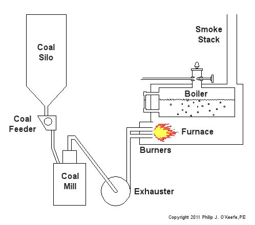
Human lungs, along with the diaphragm which works to expand and release the lung cavities, enable our bodies to breathe in air, then expel the waste product, carbon dioxide. Oxygen is needed to metabolize, that is burn, our food, enabling the food cells’ energy to be absorbed by our bodies and converted into energy to live. Like us, coal power plants need to breathe in oxygen in order to convert coal’s latent energy into a usable form. Previously we learned how coal is fed to a coal mill where it is pulverized into a fine powder. This powder is then sucked out of the mill by the exhauster and blown through a serpentine path of pipes leading to the burners on the furnace. The burners will then act upon the coal, combining it with the oxygen in our atmosphere to create a chemical reaction capable of releasing coal’s energy in the form of heat. All this activity looks to a bystander like a massive, sustained fire in the furnace. See Figure l.
Figure 1 – Coal Power Plant Combustion The boiler is contained within the furnace and is situated so it is exposed to fire from the combustion process. Heat energy from the fire transfers into the water in the boiler, much like when you boil water for tea in a kettle on your stovetop. If you’ve ever boiled water, you know that once it gets hot enough it will turn into steam, and the same for our furnace boiler. The steam emitting from the boiler will cause a turbine-generator to spin, and the end result will be electricity for our use. In the simple diagram of Figure 1, waste products from the combustion process, like carbon dioxide, go up the smoke stack and are released into the atmosphere. Incidentally, this is the same type of carbon dioxide that we exhale from our bodies when we breathe. Please keep in mind that Figure 1 is a very simplified diagram. In reality waste products leaving the furnace go through various pollution control devices where most pollutants are removed before they reach the smoke stack. These details, and many more, are the type of information that would be covered during my training seminar, Coal Power Plant Fundamentals. Next time we’ll learn how the heat energy in steam is converted into mechanical energy capable of spinning a turbine generator to make electricity.
_____________________________________________
|


Transformers and The Magic of Electricity
Sunday, December 5th, 2010| No, the next series of articles is not about those talking, morphing, gigantic killing machines that children love to play with. We’re going to talk about the type that adults just can’t live without.
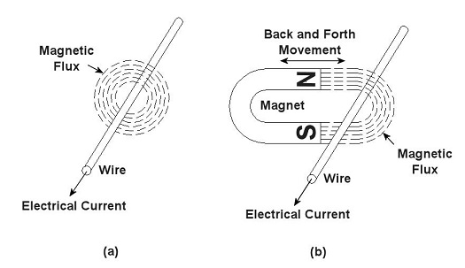
You’ve probably heard the term “electrical transformer” at some point, but you may not be entirely sure what is meant by it. Most don’t realize that they use them all the time, like when they recharge their cell phone battery. That little black box that plugs into the wall outlet is one of them, and what they do is perform the important task of reducing the 120 volts of power that fuels your home’s outlets down to a lower voltage level, for example, 12 volts, which can be used by small electronic devices. But before I explain how this reduction process works we need to understand magnets. Magnets, those wonderful curiosities that mesmerized you as a kid, keeping you busy for hours picking up nails and paper clips, have many practical applications, although they weren’t considered to be anything more than amusing novelties until the early 19th Century. That’s when a French scientist by the name of André-Marie Ampére studied the relationship between magnetism and electricity. What he found was that when an electrical current is run through a wire it turns into a magnet. Ampere’s work was then built upon by British scientist Michael Faraday. He discovered that electric current passing through wire creates magnetic lines of flux that encircle the wire as shown in Figure 1 (a). Faraday also discovered that if you move a magnet back and forth near a wire, as shown in Figure 1 (b), you can generate an electrical current in the wire.
Figure 1 – Relationships Between Electricity and Magnetism Why does this happen? Well, magnets work as they do because they have a magnetic north (N) and south (S) pole, and lines of magnetic flux extend from one pole to the other. You can actually see these lines of flux if you sprinkle iron filings between the poles. The iron filings are attracted to the magnet and align themselves along the lines as shown in Figure 2. When the lines of flux move through the wire, they induce an electrical current in it. As long as you keep the magnet moving back and forth, lines of flux will continue to pass through the wire, and the current will keep flowing. When the magnet stops moving, the current in the wire also stops.
Figure 2 – Iron Filings Aligned Along Lines of Magnetic Flux Faraday soon began experimenting with coiled wires and iron rods. He wanted to see how electrical current flowing through one coiled wire would affect another coiled wire in close proximity. His basic experimental setup is shown in Figure 3.
Figure 3 – Michael Faraday’s Experiment Faraday’s experiment consisted of two insulated wires, each coiled around an iron rod. The first coiled wire ran to a battery and then a switch. The switch enabled Faraday to connect and disconnect the battery to the first coil during his experiments. The second coiled wire was connected to an instrument called a Galvanometer, which measures the amount of electricity flowing through the wire. When the switch was closed, connecting the first coil to the battery, Faraday noticed that the Galvanometer’s indicator needle moved, then returned to zero. Somehow the electricity flowing from the battery to the first coil was causing an electric current to momentarily flow in the second coil. But how does electricity flow from one coil to the other if they’re not connected? It doesn’t. What’s actually taking place is known as “electromagnetic induction.” Faraday’s experiment enabled him to conclude that current flowing through the first coil set up lines of magnetic flux in the iron rod to which both coiled wires were attached. When the switch was closed, the lines of magnetic flux built in intensity until they induced a current in the second coil. But when the magnetic flux reached its full intensity, and stayed at full intensity, the current induced in the second coil stopped flowing. Faraday’s initial confusion as to the state of affairs soon changed into the Eureka! moment of discovery, and he was able to conclude that current will flow in the second coil only if the lines of magnetic flux are fluctuating in intensity. Next week we’ll see how an as yet undiscovered young inventor used the results of Faraday’s experiment to build the first electrical transformer. _____________________________________________ |
Coal Power Plants, Far From Perfect
Sunday, July 18th, 2010|
Did you know that even a perpetual motion machine will eventually come to a stop due to uncontrollable factors? Well, uncontrollable factors are at play in power plants, too. If you recall from our last article, heat rate is industry jargon for gauging how efficiently a coal-fired power plant is operating. We learned that heat rate can be affected by things like missing thermal insulation on pipes and equipment. Missing insulation is, of course, a thing that is under human control and easily corrected, but there are some things that affect heat rate that we just can’t do anything about. They’re called, appropriately enough, uncontrollable factors. Uncontrollable factors exist because anything devised and made by fallible humans who are beholden to the myriad laws of the universe cannot be 100 percent efficient. At their best utility coal fired power plants have an overall efficiency of between 30 and 40 percent. That means 60 to 70 percent of the energy available in the coal gets lost in the process of generating electricity. A terrible waste, right? And yet there’s nothing we can do to trim these losses until improvements in the present level of technology take place. Just as our ability to track microbes is dictated by the strength and accuracy of our magnifying equipment, so are we hampered by the tools we have at our disposal to deal with inefficiencies such as energy losses. So where does this energy get lost due to uncontrollable factors? The first and probably most obvious place to look is the smoke stack. Energy is also lost in three other ways: friction between equipment parts, auxiliary power consumption, and in a piece of equipment known as a condenser. Let’s look at each. In the most basic of terms, when coal is introduced into a power plant boiler it is combined with air and burned. This burning process releases heat energy, but it also forms gases that contain nitrogen and compounds like carbon monoxide and carbon dioxide. There’s also some water vapor formed by moisture in the coal and air. These gases and vapor absorb some of the heat energy released. To keep the combustion process going the gases and vapor must be removed from the boiler by powerful fans and sent up the smoke stack. Now, boilers are designed to absorb much of the heat energy from the gases and vapor that make their way to the stack, but they cannot possibly absorb it all. The result is that a significant amount of heat escapes up the smoke stack into the atmosphere along with the gases. Friction between parts is present everywhere in a power plant. It exists in the bearings on the shafts of motors, pumps, and steam turbines, slowing them down and hindering their operating capacity. Friction also exists where moving water and steam are present, impeding their ability to flow through piping systems. There is even friction working against the steam as it flows through parts in the turbine. Extra energy has to be expended to overcome this friction. This is energy that could be used to generate electricity. Now at some point in your life you’ve probably heard it said, “You need money to make money,” and this is very true. It takes a certain investment of resources to produce a profit-making enterprise. This investment principle holds true for the making of electricity, too. The bottom line is you need electricity to make electricity. Specifically, you have to use significant amounts of electricity to power machinery that is essential to move coal, air, combustion gases, and water through the process of making electricity in the power plant. This is called auxiliary power. It’s the electricity siphoned off by the various pieces of equipment in a power plant in its quest to generate electrical energy to be sold to customers. Another major factor at play in uncontrollable energy losses is in a piece of equipment integral to the very function of power plants: the condenser. It comes into play when water is boiled to make steam which then travels through the turbine, spinning its electrical generator and creating electric power. Unfortunately even the most efficient of steam turbines cannot use 100% of the heat energy coming at it from the steam. You see, after steam leaves the turbine, it’s turned back into water by a condenser so it can be sent back to the boiler to be turned into steam again. One of the reasons that this is done is so that the boiler does not have to be continuously filled with fresh, purified water. Water purification is necessary to keep minerals, seaweed, fish scales, and other nasty things from clogging up and damaging the boiler and steam turbine, and purified water is not as readily available as, say, lake water. The condenser acts as a heat exchanger that is hooked up to the steam turbine exhaust. It has tubes inside of it in which cold water flows, water which is drawn in from a nearby body of water, most often a river or lake. As steam blows across the outside of the cold water tubes in the condenser, it gives up its remaining heat energy and condenses into water again, then it is returned to the boiler to repeat its journey. The river water within the tubes of the condenser flows back into the river, carrying with it the heat energy removed from the steam. That wraps up our discussion about coal power plant efficiency. Next time we’ll discuss a new topic: coal fired power plant furnace explosions. _____________________________________________ |


