Posts Tagged ‘engine’
Friday, December 15th, 2017
|
Last time, we learned that a crankshaft is an engineering device which converts the reciprocating linear motion of an engine’s back-and-forth moving piston into the rotary motion that powers externally attached machinery. Its movement is shown here,
A Crankshaft in Motion
We’ll see how a crankshaft and piston’s motion benefits by the use of a flywheel next time.
opyright 2017 – Philip J. O’Keefe, PE
Engineering Expert Witness Blog
____________________________________ |
Tags: crankshaft, cylinder, engine, engineering, flywheel, machinery, piston, reciprocating linear motion, rotary motion
Posted in Engineering and Science, Expert Witness, Forensic Engineering, Innovation and Intellectual Property, Personal Injury, Product Liability | Comments Off on A Crankshaft in Motion
Friday, November 24th, 2017
|
Last time we discussed how torque is created as a flywheel spins. This torque is a factor of the flywheel’s moment of inertia, which is dependent on how far the masses of the flywheel’s parts are located from its center of rotation. Today we’ll present a formula to compute how much horsepower is required to accelerate a flywheel. And here it is,

Horsepower Required to Accelerate a Flywheel
where, T is the torque created on the flywheel’s shaft in units of inch-pounds. The term n is the flywheel shaft’s speed of rotation in revolutions per minute, RPM. Horsepower, HP, is engineering shorthand for a unit of power equal to 6600 inch-pounds per second, and the number 63,025 is a constant needed to convert torque, T, and the spinning shaft’s rotations per minute, RPM, into horsepower units.
Torque is present whether the flywheel’s spin accelerates or decelerates. During acceleration torque is created, which contributes to the production of kinetic energy that’s stored inside the flywheel. When a flywheel’s spin decelerates, its mass experiences the effects of negative acceleration, and stored kinetic energy is released.
As we learned awhile back, horsepower is a function of torque in any moving machinery, including engines and flywheels. An engine must produce horsepower to accelerate a flywheel connected to its shaft. By the same token, when the engine’s horsepower output diminishes or stops, the flywheel begins to decelerate. This deceleration causes kinetic energy stored within the flywheel to be released, providing horsepower necessary to keep the engine and flywheel spinning. That is, until the power output of the engine returns or the stored kinetic energy of the flywheel is ultimately exhausted.
We’ll see how that works next time when we take a look inside a reciprocating engine.
opyright 2017 – Philip J. O’Keefe, PE
Engineering Expert Witness Blog
____________________________________ |
Tags: acceleration, deceleration, engine, engineering, flywheel, horsepower, kinetic energy, mass, moment of inertia, torque
Posted in Engineering and Science, Expert Witness, Forensic Engineering, Innovation and Intellectual Property, Personal Injury, Product Liability | Comments Off on Horsepower Required to Accelerate a Flywheel
Friday, June 23rd, 2017
|
Belts are important. They make fashion statements, hold things up, keep things together. Today we’re introducing a scenario in which the Euler-Eytelwein Formula will be used to, among other things, determine the ideal width of a belt to be used in a mechanical power transmission system consisting of two pulleys inside a hydroponics plant. The ideal width belt would serve to maximize friction between the belt and pulleys, thus controlling slippage and maximizing belt strength to prevent belt breakage.
An engineer is tasked with designing an irrigation system for a hydroponics plant. Pulley 1 is connected to the shaft of a water pump, while Pulley 2 is connected to the shaft of a small gasoline engine.
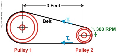
What Belt Width does a Hydroponics Plant Need?
Mechanical power is transmitted by the belt from the engine to the pump at a constant rate of 4 horsepower. The belt material is leather, and the two pulleys are made of cast iron. The coefficient of friction, μ, between these two materials is 0.3, according to Marks Standard Handbook for Mechanical Engineers. The belt manufacturer specifies a safe working tension of 300 pounds force per inch width of the belt. This is the maximum tension the belt can safely withstand before breaking.
We’ll use this information to solve for the ideal belt width to be used in our hydroponics application. But first we’re going to have to re-visit the two T’s of the Euler-Eytelwein Formula. We’ll do that next time.
Copyright 2017 – Philip J. O’Keefe, PE
Engineering Expert Witness Blog
____________________________________ |
Tags: belt, belt breakage, coefficient of friction, engine, engineer, horsepower, leather belt, mechanical power transmission, pulley, pump
Posted in Engineering and Science, Expert Witness, Forensic Engineering, Innovation and Intellectual Property, Personal Injury, Product Liability | Comments Off on What Belt Width does a Hydroponics Plant Need?
Sunday, January 19th, 2014
|
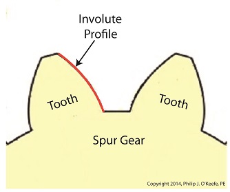
Last time we learned how spur gears mesh together to form a gear train and we examined a train consisting of just two gears, one being the driving gear, the other the driven gear. Today we’ll take a look at the geometry behind the smooth functioning of modern spur gear teeth when we identify their peculiar shape to be that of an involute curve.
The curved profile of spur gear teeth conforms to a type of mathematical curve found in geometry known as an involute. The involute profile of a spur gear tooth is shown in red below.

The mathematical notion of the involute was first presented in 1673 by Dutch mathematician Christiaan Huygens, in his book, Horologium Oscillatorium. Huygens’ book presents his studies on clock pendulums and the applied mathematics he used in an effort to predict their often erratic motion on ships at sea. His book ultimately dealt with far more than this, resulting in a treatise on the mathematical properties of the involutes of curves.
To see how an involute curve is formed, we’ll conduct a simple experiment. One end of string is attached with a tack to a circular object, like the yellow rod shown in the following illustration. The other end of string has a red ball attached to it.
 Forming An Involute Curve If we grab the ball and pull the string taught while wrapping the string around the rod, the ball’s path will form an involute curve due to the incremental shortening of the string that occurs as it wraps around the rod.
Next time we’ll see how the involute profile of gear teeth contributes to efficient mechanical energy transmission in gear trains.
_______________________________________ |
Tags: axle, Chritiaan Huygens, driven gear, driving gear, electric motor, engine, engineering expert witness, forensic engineer, gear expert, gear teeth, gear train, gears, gears mesh, involute, involute curve, locomotive, mechanical device, mechanical energy, mechanical engineering expert, mesh, powering device, railroad expert witness, shaft, spur gears, traction motor, train, wheels
Posted in Engineering and Science, Expert Witness, Forensic Engineering, Innovation and Intellectual Property, Personal Injury, Product Liability | Comments Off on Spur Gear Tooth Geometry and the Involute Curve
Monday, January 13th, 2014
|
Last time we covered the basic terminology of spur gears. Today we’ll see how they interact with one another to form a gear train, such as the one depicted below.
 Meshing Spur Gears Form A Gear Train A gear train is formed when the teeth of two or more gears mesh and work together for the purpose of powering a mechanical device.
A gear train can consist of as little as two gears, but trains can be so large as to contain dozens of gears, depending on the complexity of the device they are powering. But no matter how many gears are employed, there are certain key features that are shared by every gear train assembly. First, one gear within the train must be attached to a shaft rotated by a source of mechanical energy, such as an engine or electric motor. This gear is called the driving gear.
The second requirement of a gear train is that at least one gear other than the driving gear is mounted to the shaft of a rotating machine part. This gear is called the driven gear.
 Locomotive Gear Train Consisting Of Two Gears The illustration above shows an exploded view of a locomotive gear train assembly consisting of two gears. The driving gear is mounted to the shaft of an electric traction motor. The driven gear is mounted to the locomotive’s axle.
When a motor is attached to the axle, the two gears mesh together. The traction motor converts electrical energy into mechanical energy, which is supplied to the driving gear via the spinning motor’s shaft. The teeth of the driving gear then transmit the motor’s mechanical energy to the teeth of the driven gear, which then turn the locomotive’s wheels. It’s just one of countless operations that can be performed with gear train assemblies.
Next time we’ll examine the geometry behind modern spur gear tooth design.
_______________________________________ |
Tags: axle, driven gear, driving gear, electric motor, engine, engineering expert witness, forensic engineer, gear expert, gear teeth, gear train, gears, gears mesh, locomotive, mechanical device, mechanical energy, mechanical engineering expert, mesh, powering device, railroad expert witness, shaft, spur gears, traction motor, train, wheels
Posted in Engineering and Science, Expert Witness, Forensic Engineering, Innovation and Intellectual Property, Personal Injury, Product Liability | Comments Off on Gear Trains
Monday, December 16th, 2013
|
Ever wondered if a running horse lifts all four of its feet off the ground at the same time? Leland Stanford, an industrialist and horseman of the late 19th Century did, and he hired photographer Eadweard Muybridge to find out. Muybridge’s series of 24 photographs of Stanford’s horse, Sallie Gardner, came to be known as Sallie Gardner at a Gallop and is regarded to be an early example of silent film.

The Muybridge photos were viewed at increased speed on a zoopraxiscope, a device he invented in 1879. A precursor to modern movie projectors, it projected a series of independent photographs as a moving image through the use of multiple cameras shooting the subject at different points in time. In this way it was disclosed that yes, indeed, there were moments when all four of a galloping horse’s feet hover in mid air. Today’s moving images are displayed at between 24 and 300 fps, depending on the application.
Muybridge’s experiment proved that not only are moving images more engaging than static ones, they are also more explicit, able to convey information still images are not. Take for example this series of stills of a centrifugal clutch assembly.

Are you able to tell by looking at these two-dimensional images how a clutch works? How as the engine speeds up the spinning shoes move out and make contact with the clutch housing, this pressure causing the entire assembly to spin? Unless you’re familiar with clutches, probably not.
Now here’s the same clutch brought to life through animation:
In today’s fast paced, internet-laden society, people’s attention spans are shorter than ever, and their demands to be visually engaged are high. It’s been proven that holding a modern day viewer’s attention for more than three seconds is a difficult task. This truth is evident in the courtroom as well, where trial attorneys are obliged to increase the production value of evidence presented in order to win over juries, and animation is becoming their tool of choice.
What held true more than 100 years ago still holds true today: Nothing tells a story like a moving image.
Next time we’ll switch gears, quite literally, to understand how a series of gears work together to power machinery.
________________________________________
Note: If you are viewing this blog article in an email and the animation video does not appear, then click on this link to view the article with your web browser.
________________________________________
|
Tags: 3D animations, animation, centrifugal clutch, clutch, courtroom demonstratives, cutter head, engine, engineering expert witness, forensic engineer, grass trimmer, hand held grass trimmer
Posted in Courtroom Visual Aids, Engineering and Science, Expert Witness, Forensic Engineering, Innovation and Intellectual Property, Personal Injury, Product Liability | Comments Off on See How a Centrifugal Clutch Works With Animation
Sunday, April 28th, 2013
|
During 6th grade science we had a chapter on Simple Machines, and my textbook listed a common lever as an example, the sort that can be used to make work easier. Its illustration showed a stick perched atop a triangular shaped stone, appearing very much like a teeter-totter in the playground. A man was pushing down on one end of the stick to move a large boulder with the other end. Staring at it I thought to myself, “That doesn’t look like a machine to me. Where are its gears?” That day I learned about more than just levers, I learned to expect the unexpected when it comes to machines.

Last time we learned that under patent law the machine referred to in federal statute 35 USC § 101 includes any physical device consisting of two or more parts which dynamically interact with each other. We looked at how a purely mechanical machine, such as a diesel engine, has moving parts that are mechanically linked to dynamically interact when the engine runs. Now, lets move on to less obvious examples of what constitutes a machine.
Would you expect a modern electronic memory stick to be a machine? Probably not. But, under patent law it is. It’s an electronic device, and as such it’s made up of multiple parts, including integrated circuit chips, resistors, diodes, and capacitors, all of which are soldered to a printed circuit board where they interact with one another. They do so electrically, through changing current flow, rather than through physical movement of parts as in our diesel engine.
A transformer is an example of another type of machine. An electrical machine. Its fixed parts, including wire coils and steel cores, interact dynamically both electrically and magnetically in order to change voltage and current flow.
Electromechanical, the most complex of all machine types, includes the kitchen appliances in your home. They consist of both fixed and moving parts, along with all the dynamic interactions of mechanical, electronic, and electrical machines.
Next time we’ll continue our discussion on the second hurtle presented by 35 USC § 101, where we’ll discuss what is meant by article of manufacture.
___________________________________________
|
Tags: 35 USC § 101, 35 USC Section 101, capacitor, current flow, diode, electrically, electromechanical device, electronic, electronic device, engine, engineering expert witness, gears, integrated circuit chip, kitchen appliances, machine, machine design, magnetically, moving parts, patent eligibility, patent law, printed circuit board, resistor, simple machine, steel cores, Title 35 United States Code, transformer, utility patent, voltage, wire coils
Posted in Engineering and Science, Expert Witness, Innovation and Intellectual Property, Product Liability, Professional Malpractice | Comments Off on Determining Patent Eligibility – Part 4, Machines of a Different Kind
Sunday, June 3rd, 2012
| My first car was a used 1963 Dodge 880. It was reliable for the most part, but one day when I stepped on the brake in a supermarket parking lot, nothing happened. I began to roll down an incline, and I struggled to steer around the maze of parked cars in the lot. After what seemed to be an eternity I managed to navigate my way out of the lot into an adjacent cornfield. The soft ground and corn stalks finally brought me to a stop. I later discovered that the reason my brakes failed is because their linings had completely worn away.
Like the brakes in cars, centrifugal clutch shoes also have linings as shown in Figure 1. Brake linings are typically made of a rough, high friction materials, such as ceramic compounds. These materials are bonded to the brake shoes, or in the case of clutches, to the clutch shoes. When centrifugal force comes into play, pressing the clutch shoes against the inside wall of the clutch housing, the roughness of the linings provides a good grip, preventing slippage between the shoes and the housing.

Figure 1
As we learned in previous articles, slip between the clutch shoes and clutch housings can create problems. In our grass trimmer for example, we learned that slippage reduces the amount of power the engine can effectively transmit to the cutter head. It also tends to produce a lot of heat. This heat can adversely effect the clutch springs and cause clutch failure.
Although the high friction lining of the clutch shoes prevents most slippage, it can still occur, as when the throttle is depressed and engine speed increases beyond idle. There is some slipping as the clutch shoes first engage with the clutch housing, and it will continue until the engine speed increases to the point where centrifugal force causes the clutch shoes to firmly press into the clutch housing.
Slippage also occurs when gasoline powered tools are subjected to operating stress. Figure 2 shows two views of a chainsaw. The first view is complete, the second shows the chain and clutch housing in isolation.

Figure 2
With the engine housing removed, we see that the saw chain is connected to a sprocket located on the centrifugal clutch housing. This sprocket is similar to those that engage the chains on bicycle wheels.
Now suppose someone decides to use the chainsaw to cut a green, sap-filled log. To make matters worse, let’s suppose the chainsaw has a dull saw chain. If you’ve ever tried doing this, you know that the sticky, sappy wood will eventually gum up the chain and stop it from moving. Since the chain is connected to the clutch housing, it stops as well. However the clutch shoes, which are driven by the engine, keep trying to move the gummed-up clutch housing, because the engine’s power is enough to overcome some of the friction. The result is that the shoes slip uselessly inside the housing.
Over time, continued slippage will cause the clutch shoes’ high friction lining to wear away. Once the lining is gone the clutch shoes will slip excessively, even when the gasoline powered tool is being employed to perform the lightest task. That’s because slipping prevents a good portion of the engine’s power from being transmitted to the cutting head.
That’s it for our series on centrifugal clutches. Next we’ll be discussing transistors, how they’re used in electronic controls to switch things on and off and perform other functions.
____________________________________________
|
Tags: brakes, centrifugal clutch, centrifugal force, chainsaw, clutch, clutch failure, clutch housing, clutch shoe, clutch shoe lining, clutch slip, clutch spring, cutter head, engine, engineering expert witness, forensic engineer, friction, gasoline engine, gasoline powered tools, grass trimmer, power transmission, saw chain, sprocket, throttle trigger, wear
Posted in Engineering and Science, Expert Witness, Forensic Engineering, Innovation and Intellectual Property, Personal Injury, Product Liability | Comments Off on Mechanical Power Transmission – Centrifugal Clutch Shoe Wear
Sunday, May 20th, 2012
|
I got my first 10-speed bike when I was in high school. It was nice, except for one nasty hangup, the brakes were always going out of adjustment. Once it did this at the worst of times, when I was going down a steep hill. I squeezed hard on the brake handles, and nothing happened. The bike started to go out of control in its ascent down the hill, and in desperation I took my feet off the pedals and pressed the soles of my shoes as hard as I could into the road surface. To my relief my emergency measure was effective. The harder I pressed into the pavement, the less my shoes slipped, and the more the bike slowed down. I had good rubber treads on the sneakers I was wearing that day, and the friction between the soles of my shoes and the surface of the pavement was strong enough to stop my runaway descent. Something very similar occurs during the operation of a centrifugal clutch.
If you recall from previous articles in this series, when the clutch mechanism spins faster than engine idle speed, the centrifugal force acting upon the clutch shoes overcomes the tension in the springs. This causes the clutch shoes to make contact with the clutch housing. But although there is contact, the clutch shoes will initially slip somewhat. That is, the clutch housing and cutter head won’t spin at exactly the same speed when a faster spin is first employed, although the slip between the clutch shoes and housing decreases as engine speed increases.
Faster speed means there’s more centrifugal force at play, forcing the shoes harder against the drum of the clutch housing. The increase in centrifugal force makes the shoes move tighter and tighter against the housing, and this causes an increase in friction. Eventually the engine speed will increase to full throttle, the point where the shoes are pressed into the housing so hard there is no more slip. The cutter head will then turn at the same rate as the engine, and the engine’s power will be fully transmitted to the cutter head, allowing you to trim grass effectively.
Friction is a double edged sword. On the one hand it reduces slip between the clutch shoes and clutch housing. On the other, the friction between the slipping shoes and clutch housing generates a lot of heat, particularly if the grass trimmer is cutting thick grass. We’ll see how that heat impacts the clutch mechanism components next week.
____________________________________________

|
Tags: centrifugal clutch, centrifugal force, clutch housing, clutch mechanism, clutch shoe, clutch slip, clutch spring, cutter head, engine, engineering expert witness, forensic engineer, friction, frictional heat, full throttle, grass trimmer, heat, power transmission
Posted in Engineering and Science, Expert Witness, Forensic Engineering, Innovation and Intellectual Property, Personal Injury, Product Liability | Comments Off on Mechanical Power Transmission – The Centrifugal Clutch and Friction
Sunday, May 6th, 2012
| Energy, or power, requires direct contact to transfer. In most cases. One notable exception to this rule of physics that I know of is the martial art of Tai Chi. But when we’re talking golf, for example, if you don’t’ make contact with that ball, it ain’t gonna fly, no matter how many swings you take.
Last time we looked at a gas powered trimmer’s engine, centrifugal clutch mechanism, clutch housing, and cutter head and how they’re assembled together. With the centrifugal clutch assembled into the grass trimmer, let’s refer to Figure 1 to see what it looks like when we start the engine and run it at low, idle speed.

Figure 1
Figure 1 represents a view from the back of the clutch housing, revealing the centrifugal clutch housing inside. At idle speed there are only a few millimeters of space between the blue clutch mechanism shoes and red clutch housing, but the important point is that they’re not touching the clutch housing. Because they’re not, the engine’s power can’t be transferred from the engine to the clutch housing, and it remains stationary, that is, the clutch housing doesn’t spin. Since the grass trimmer’s cutter head is coupled to the clutch housing, it also remains stationary.
Figure 2 shows what happens from the same viewpoint when we press the throttle trigger, making the engine spin at operational speed.

Figure 2
With the engine spinning faster the centrifugal force, Fc, acting upon the clutch shoes overcomes the tension of the clutch mechanism springs, and the shoes move away from each other along the green boss. They will eventually make contact with the clutch housing, enabling power from the engine to transfer to the clutch housing via the centrifugal clutch mechanism. The clutch housing and cutter head spin along with the engine, and we can now cut grass.
When we let go of the engine’s throttle trigger it again slows to idle speed, the shoes no longer touch the insides of the clutch housing, and the housing and cutter head stop spinning, as we saw in Figure 1.
Next time we’ll talk about centrifugal clutch failures, things that can go wrong with them and keep them from operating properly.
____________________________________________
|
Tags: boss, centrifugal clutch, centrifugal clutch assembly, centrifugal force, clutch housing, clutch mechanism, clutch shoe, cutter head, engine, engine power transmission, engine throttle trigger, engineering expert witness, forensic engineer, gas powered trimmer, gasoline engine, grass trimmer, idle speed, power transfer, spring
Posted in Engineering and Science, Expert Witness, Forensic Engineering, Innovation and Intellectual Property, Personal Injury, Product Liability | Comments Off on Mechanical Power Transmission – The Centrifugal Clutch Powers Up


