|
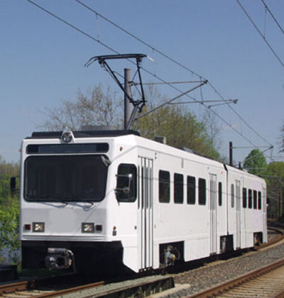
Have you ever been stranded on a subway car? The lights flickered wildly, then the odd humming sounds all came to an abrupt stop, and you sat there exchanging uncomfortable glances with your fellow passengers? “Hey, get this thing going! I’ve got an appointment to make!” someone shouts at the driver, sequestered in his cab. The trouble is, he, like the rest of the passengers, is equally helpless in this situation. You see, streetcars, subway cars, and light rail cars are all forms of electric railway cars, and when their source of electricity goes out, so do they. They’re similar to the diesel-electric locomotive we looked at last week because they use electric traction motors for propulsion, meaning to move forward. But their difference lies in the fact that electric rail cars don’t carry their own source of power and are entirely reliant on an external source, an electrical substation. See Figure 1 below.
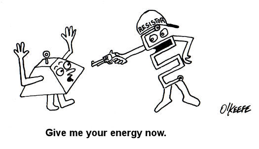
Figure 1 – Electric Railway Car Propulsion System This substation performs the task of taking the power provided by an electric utility power plant and converting it into a form of power that the electric rail car can use to operate its traction motors. The two are connected via a trolley wire and the two rails that the car runs on. The railway car has a spring-loaded arm called a pantograph on its roof that touches the trolley wire, allowing electrical current to flow into a speed control system housed under the car. This speed control system performs the task of varying the flow of electrical current to the traction motors, enabling the car to move, before it eventually exits the motor through its wheels, then back to the substation where it originated, thus completing an electrical circuit. Many newer electric railway cars couple a regenerative braking system with a mechanical one. Their operation is similar in nature to a dynamic braking system where the traction motors are turned into generators. The difference is that with regenerative braking systems the current from the traction motors is sent to the trolley wire through the pantograph as shown in Figure 2 below.
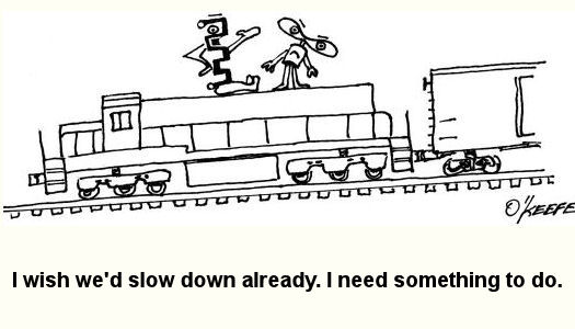
Figure 2 – An Electric Railway Car Using Regenerative Brakes This diagram shows the railcar generating electricity, but it may not be so obvious how its motion is made to slow down, after all, we see no resistor grids like we did in last week’s illustration of a dynamic braking system. So how does it stop? The trick here is that there are other cars running on the rail line at the same time which are using electrical current to move forward. So what does this have to do with stopping it you ask? Let’s take a look at Figure 3 for clarification. Figure 3 – How Regenerative Brakes Help Save Power In this illustration we see that as Car A goes downhill and the operator applies the brakes, the regenerative brake will be caused to start pumping electrical current into the trolley wire. Now, if Car B is on the same rail line going up the other side of the hill, it will need power to climb that hill, and it will need to draw that power from the trolley wire by way of its pantograph. But instead of drawing all its electrical current from the substation, Car B will first draw off the current produced by nearby Car A, and only then will it draw the remainder of its power requirements from the substation. During this braking process the kinetic energy in Car A is converted into electrical energy by its traction motors. Then Car B uses its own traction motors to convert the electrical energy drawn from Car A into mechanical energy, enabling it to climb the hill. Car B has effectively robbed Car A of its energy, so Car A slows down. As we discovered last week during our discussion of dynamic brakes, regenerative brakes become ineffective below a certain minimum speed. This is the reason that electric rail cars need mechanical brakes to complete the job of stopping. We see that the regenerative braking process is actually quite green. It allows for electrical energy that would normally be wasted as heat energy escaping into the atmosphere to be converted into useful energy, taking a significant chunk out of the demand for new energy off of substations. It also helps the electric railway to save money when it comes time to paying the electric bills. You may have noticed a copyright symbol and my name included in this week’s illustrations. That’s because it has recently come to my attention that many of my readers are unaware that I am the CAD (Computer Aided Design) artist who creates the illustrations featured in most of my blogs. CAD is a useful tool in explaining difficult technical subject matter, which is precisely why I use it so often. Next week we’ll explore in more depth the benefits of using this tool.
_____________________________________________
|
Posts Tagged ‘mechanical brake’
Regenerative Brakes
Sunday, June 13th, 2010


Brakes and Braking Systems
Sunday, May 23rd, 2010|
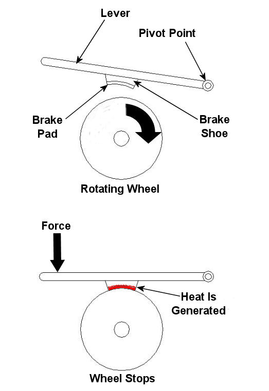
Imagine driving in your car, you’re traveling at a speed of 65 mph and you’re coming up on a curve. You depress your brake pedal to negotiate the turn, and nothing happens… Scenarios just like this one have been in the news quite often lately, brakes which just aren’t operating correctly. We’ve heard the tales of terror, recounted by those unfortunate individuals who have been placed in this situation, but have we reflected on just why their brakes might have failed? Put most simply, a brake is a device whose purpose is to stop a body in motion. This important task is accomplished by converting the kinetic energy (energy of motion) into heat energy. This can be accomplished by either of two methods, mechanically or electrically. In today’s blog we’ll focus on the mechanical aspect. A simple mechanical brake is shown in Figure 1 below. In this arrangement kinetic energy is converted into heat energy when force is applied to a lever, causing a brake shoe to meet up with a rotating wheel. The brake shoe has a pad attached to its surface that makes direct contact with the wheel, and when the two come together great friction is produced. It’s this friction that will ultimately stop the object in motion. Friction turns the kinetic energy into heat energy.
Figure 1 – A Simple Mechanical Brake Friction at its simplest is a mechanical resistance to movement. Whenever two materials in motion come into contact with each other there is always some degree of friction. The extent to which friction is produced by their meeting is referred to as the “coefficient of friction.” The coefficient of friction varies according to the surface character of the materials coming in contact. For example, the coefficient of friction for the leather sole of your shoe on smooth ice is very low. This means you’ll do a lot of slipping when you’re trying to walk, and that’s because ice presents little friction to resist a smoothly soled shoe. But take this same shoe and apply it to the rough surface of concrete, and you’ll be walking quickly and efficiently. Coefficients of friction between different materials have been duly measured in laboratories and are tabulated for easy access in engineering reference books. Based on our simple example above, one would easily come to the conclusion that a high coefficient of friction is desirable when talking about brake shoes, specifically the one represented in Figure 1 above. The higher the coefficient of friction, the more the pad wants to grab the wheel, and the less force you will need to apply to the brake shoe to successfully come to a stop. That’s mechanical braking in a nutshell. Next time, we’ll focus on an electrical braking system known as a “dynamic brake.” _____________________________________________
|


