|
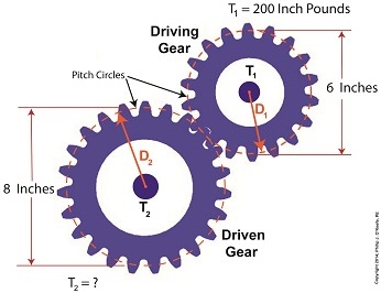
Last time we set up an example where an electric motor is connected to a lathe via a gear train. Today we’ll take the numerical values present on that gear train and plug them into the torque ratio equation we’ve been working with for the past few blogs. In the illustration below the electric motor exerts 200 inch pounds of torque upon the driving gear. The driving gear pitch circle diameter is 6 inches, while the driven gear pitch circle diameter is 8 inches. It’s been determined through previous lab testing that the lathe we’ll be using requires at least 275 inch pounds of torque to be exerted upon the driven gear shaft in order to operate properly. Will the gear train shown below meet this requirement? First, a review of the torque ratio equation: T1 ÷ T2 = D1 ÷ D2 Now we’ll crunch numbers. T1 is equal to 200 inch pounds, D1 is equal to 3 inches (pitch radius equals pitch diameter divided by two), and D2 is equal to 4 inches. This gives us: (200 inch pounds) ÷ T2 = (3 inches) ÷ (4 inches) T2 = (200 inch pounds) ÷ (0.75) = 266.67 inch pounds So, does the gear train as presented here supply enough torque to power the lathe properly? No, it does not. It provides only 266.67 inch pounds, not the 275 inch pounds of torque required. Next time we’ll see how to manipulate gear sizes within a gear train in order to meet a given torque requirement. _______________________________________
|
Posts Tagged ‘mechanism’
Determining Torque Within a Gear Train
Monday, June 30th, 2014Gear Reduction Worked Backwards
Sunday, March 9th, 2014|
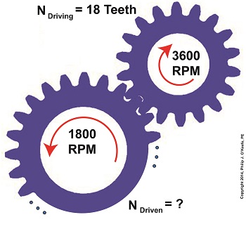
Last time we saw how a gear reduction does as its name implies, reduces the speed of the driven gear with respect to the driving gear within a gear train. Today we’ll see how to work the problem in reverse, so to speak, by determining how many teeth a driven gear must have within a given gear train to operate at a particular desired revolutions per minute (RPM). For our example we’ll use a gear train whose driving gear has 18 teeth. It’s mounted on an alternating current (AC) motor turning at 3600 (RPM). The equipment it’s attached to requires a speed of 1800 RPM to operate correctly. What number of teeth must the driven gear have in order to pull this off? If you’ve identified this to be a word problem, you’re correct. Let’s first review the gear ratio formulas introduced in my previous two articles: R = nDriving ÷ nDriven (1) R = NDriven ÷ NDriving (2) Our word problem provides us with enough information so that we’re able to use Formula (1) to calculate the gear ratio required: R = nDriving ÷ nDriven = 3600 RPM ÷ 1800 RPM = 2 This equation tells us that to reduce the speed of the 3600 RPM motor to the required 1800 RPM, we need a gear train with a gear ratio of 2:1. Stated another way, for every two revolutions of the driving gear, we must have one revolution of the driven gear. Now that we know the required gear ratio, R, we can use Formula (2) to determine how many teeth the driven gear must have to turn at the required 1800 RPM: R = 2 = NDriven ÷ NDriving 2 = NDriven ÷ 18 Teeth NDriven = 2 × 18 Teeth = 36 Teeth The driven gear requires 36 teeth to allow the gear train to operate equipment properly, that is to say, enable the gear train it’s attached to provide a speed reduction of 1800 RPM, down from the 3600 RPM that is being put out from the driving gear. But gear ratio isn’t just about changing speeds of the driven gear relative to the driving gear. Next time we’ll see how it works together with the concept of torque, thus enabling small motors to do big jobs.
_______________________________________ |
Gear Reduction
Wednesday, March 5th, 2014|
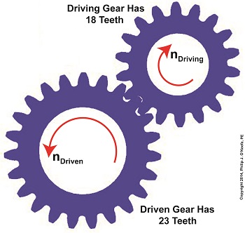
Last time we learned there are two formulas used to calculate gear ratio, R. Today we’ll see how to use them to calculate a gear reduction between gears in a gear train, a strategy which enables us to reduce the speed of the driven gear in relation to the driving gear. If you’ll recall from last time, our formulas to determine gear ratio are: R = NDriven ÷ NDriving (1) R = nDriving ÷ nDriven (2) Now let’s apply them to this example gear train to see how a gear reduction works. Here we have a driven gear with 23 teeth, while the driving gear has 18. For our example the electric motor connected to the driving gear causes it to turn at a speed, nDriving, of 3600 revolutions per minute (RPM). Knowing these numerical values we are able to determine the driven gear speed, nDriven. First we’ll use Formula (1) to calculate the gear ratio using the number of teeth each gear has relative to the other: R = NDriven ÷ NDriving R = 23 Teeth ÷ 18 Teeth R = 1.27 In gear design nomenclature, the gear train is said to have a 1.27 to 1 ratio, commonly denoted as 1.27:1. This means that for every tooth on the driving gear, there are 1.27 teeth on the driven gear. Interestingly, the R’s in both equations (1) and (2) are identical, and in our situation is equal to 1.27, although it is arrived at by different means. In Formula (1) R is derived from calculations involving the number of teeth present on each gear, while Formula (2)’s R is derived by knowing the rotational speeds of the gears. Since R is the common link between the two formulas, we can use this commonality to create a link between them and insert the R value determined in one formula into the other. Since we have already determined that the R value is 1.27 using Formula (1), we can replace the R in Formula (2) with this numerical value. As an equation this looks like: R = 1.27 = nDriving ÷ nDriven Now all we need is one more numerical value to solve Formula (2)’s equation. We know that the speed at which the driving gear is rotating, nDriving , is 3600 RPM. We use basic algebra to calculate the driven gear speed, nDriven : 1.27 = 3600 RPM ÷ nDriven nDriven = 3600 RPM ÷ 1.27 = 2834.65 RPM Based on our calculations, the driven gear is turning at a speed that is slower than the driving gear. To determine exactly how much slower we’ll calculate the difference between their speeds: nDriving – nDriven = 3600 RPM – 2834.65 RPM ≈ 765 RPM So in this gear reduction the driven gear turns approximately 765 RPM slower than the driving gear. Next time we’ll apply a gear reduction to a gear train and see how to arrive at a particular desired output speed. _______________________________________ |
Mechanical Power Transmission – Putting the Centrifugal Clutch Together
Sunday, April 29th, 2012| I’ve never been one to enjoy table top puzzles, yet I love to examine the way mechanical things fit together. Manipulating parts to see how they interrelate to form an operational system is a pastime I very much enjoy. In fact, I spend many evenings at my work bench doing just this. I often become so engrossed in the activity I forget what time it is. The result is yet another night without TV. So sad…
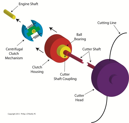
Last week we looked at how a centrifugal clutch mechanism operates when it’s coupled to a gasoline engine shaft spinning at idle speed, and then we depressed the engine throttle trigger to speed things up. Let’s now introduce a new component called the clutch housing to see how it interfaces with the clutch mechanism to drive the cutter head in a grass trimmer. Figure 1
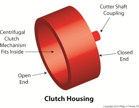
The clutch housing shown in Figure 1 resembles a rather short cup. One end is open, the other closed. Figure 2 shows the closed end of the clutch housing connected to the cutter shaft’s coupling. On the cutter shaft coupling resides a ball bearing which enables the clutch housing to both spin freely and act as a support for the clutch housing. The open end of the clutch housing allows the clutch mechanism to fit neatly inside. Figure 2
Next time we’ll put the assembly shown in Figure 2 into operation. First we’ll examine how the centrifugal clutch mechanism and clutch housing operate with the engine at idle speed, then compare that to the engine operating at actual cutting speed. ____________________________________________
|
Mechanical Power Transmission – The Centrifugal Clutch in Operation
Sunday, April 22nd, 2012| Just the other day I unexpectedly experienced the effects of centrifugal force while driving home from the grocery store. The checker had packed my entire order into one bag, making it top heavy. Then en route someone cut me off at an intersection, and I had to make a sharp turn to avoid a crash. During this maneuver centrifugal force came into play, forcing my grocery bag out of its centered position on the front seat next to me. It lurched into the passenger’s door, fell over, and spilled its contents onto the floor. Fortunately the eggs didn’t get smashed.
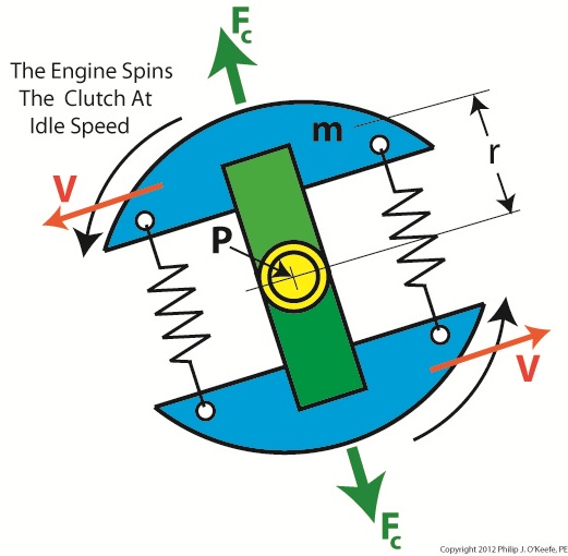
In previous articles we identified the component parts of a centrifugal clutch mechanism and learned how centrifugal force makes objects spinning in a circular path about a fixed point move outward. We can now explore what happens when we couple a centrifugal clutch mechanism to the engine of a grass trimmer. Figure 1 depicts the spinning clutch mechanism of a gas engine when it’s just been started and is operating at a slow idle speed. Figure 1
Like the red ball in my previous article on centrifugal force, the blue centrifugal clutch shoes each have a mass m. They spin around a fixed point P, situated at the center of the yellow engine shaft coupling. Point P is located a distance r from the center of each shoe. The shoes in motion have a tangential velocity V, and in accordance with Sir Isaac Newton’s Law of Centrifugal Force, the force Fc acts upon each shoe, causing them to want to pull out from the center of the mechanism, away from the fixed point. Since idle speed is rather slow, however, the centrifugal force exerted upon the shoes isn’t strong enough to overcome the tension of the two springs and the coils connecting them remain coiled, holding the shoes tightly in position on the green boss. So what happens when we press the throttle trigger on the gas engine and cause the engine to speed up? See Figure 2. Figure 2
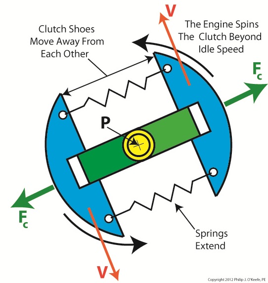
Figure 2 shows the clutch mechanism spinning at an increased velocity. The tangential velocity V increases, and according to Newton’s law, the centrifugal force Fc acting on the clutch shoes increases as well. The force is so strong that it overcomes the tension in the springs and they extend. The clutch shoes are caused to move out and away from fixed point P, as well as from each other, traveling along the ends of the boss. When we remove our finger from the throttle trigger, the engine will slow down and return to idle speed. The centrifugal force will decrease and the springs will pull the shoes back towards fixed point P. The mechanism will return to its previous state, as shown in Figure 1. Next time we’ll insert the centrifugal clutch mechanism into the clutch housing to see how mechanical power is transmitted from the engine to the cutter head in our grass trimmer. ____________________________________________
|
Mechanical Power Transmission – The Centrifugal Clutch Mechanism
Sunday, April 15th, 2012| My journey through engineering school was marked by a cast of colorful characters from around the world. I remember one Russian professor in particular, fond of extolling the virtues of Russian engineering by the statement, “In Soviet Union steel ingots roll in one door, military tanks roll out other door.” During that period of history in his homeland, it was not uncommon for all components down to the smallest screw to be manufactured within the same factory.
That professor taught me all about clutch mechanisms, and whether they’re present in Soviet tanks or grass trimmers they perform the same basic function. Let’s take a look at one now. Figure 1
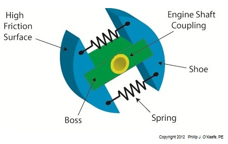
Figure l shows my color-enhanced clutch illustration, which makes it easy to identify the different components of a centrifugal clutch. The main part of the clutch is colored green and it’s respectfully referred to as the “boss.” I assume it’s earned the title due to its role in keeping all component parts of the clutch assembly together. The blue portion shows two clutch shoes. The boss fits loosely into notches within the shoes. The curved surfaces on the shoes are composed of a high friction material, and we’ll see why later. Two springs attached to the shoes cause them to pull towards each other and keep them from falling off the ends of the boss. The yellow portion shows the engine shaft coupling. It’s permanently affixed to the center of the boss. This coupling has a hole in it that enables the clutch mechanism to be attached onto an engine shaft with a threaded nut or some other type of mechanical fastener. Now that we’re familiar with a centrifugal clutch’s parts we can see how they come into play in a real world application, that of an engine shaft. We’ll explore that next week. ____________________________________________
|
Mechanical Power Transmission – Centrifugal Force and Centrifugal Clutches
Monday, April 9th, 2012| I’m not a big fan of amusement parks. The first time I rode on a Tilt-A-Whirl I was caught off guard and flung onto my side by the centrifugal force acting upon my body, the lower half of which was constrained by a seat belt so I wouldn’t be catapulted out during the ride. To make matters worse, the centrifugal force started to force the lunch I’d made the mistake of eating just before back up my throat. It was a very unpleasant experience to say the least.
Centrifugal force is an interesting phenomenon, and its principles are involved in the operation of a centrifugal clutch, which we’ll see later. For now, let’s get a basic understanding of what it’s all about, thanks to the discoveries of Sir Isaac Newton in the late 17th Century. Figure 1
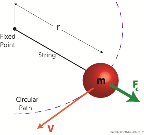
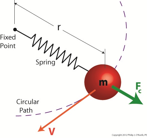
Figure 1 shows a red ball, whose mass we’ll notate m, attached to a string, the other end of which is attached to a fixed point, such as if you held it taught between your fingers. If you’re in a playful mood, you might enjoy twirling the ball above your head on its string. The distance between the center of the ball and the fixed point is labeled r, which stands for the radius of the circular path traveled by the ball as it twirls around the fixed point. The speed at which the ball travels through the air is called its straight line velocity, or tangential velocity in scientific-speak, and it is generally notated as a V. The centrifugal force, or Fc, that is exerted upon the ball as it whirls around your head is, Sir Isaac tells us, measured by the equation: Fc = mV2/r Centrifugal force in the simplest of terms is an outward-pushing force that pulls objects in motion away from the point about which they’re rotating. Let’s hold as fact that if m and r don’t change, then Newton’s equation tells us that the centrifugal force exerted upon the object in motion increases by the square of the velocity, or speed, of the ball. In other words, the faster the ball moves as you spin it around your head on the string, the harder the centrifugal force that acts upon it. As you spin the ball faster and faster, it will pull outward more and more strenuously, exerting ever greater resistance upon the string you hold between your fingers. Now suppose we replace the string in this example with a spring as shown in Figure 2. Figure 2
Why a spring? Because that’s what’s used within a centrifugal clutch. Just as with the string, the ball’s velocity increases as you increase rotation speed around the fixed point, and the centrifugal force acting upon its mass by the spinning action increases as well. The spring expands, extending further and further out from its beginning position of attachment to the fixed point, your fingers. As velocity decreases, the spring will retract, eventually returning to its original coil size. This extending and retracting action is the major mechanism at play within a centrifugal clutch. Next time we’ll explore a centrifugal clutch mechanism in more depth to observe its behavior relative to its spring under the influence of centrifugal force. ____________________________________________
|
