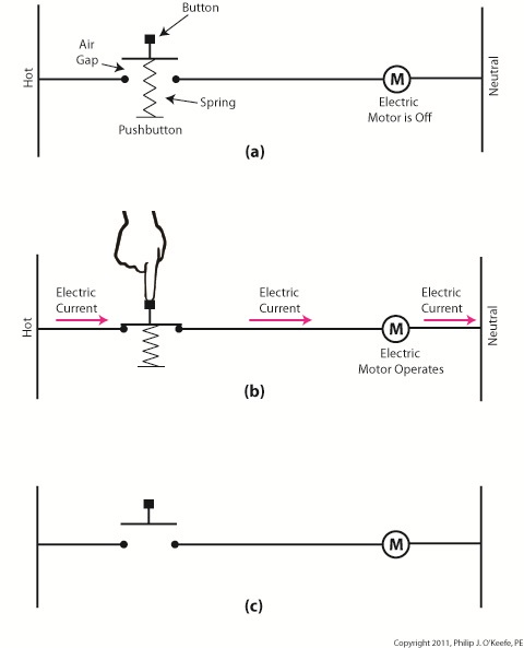
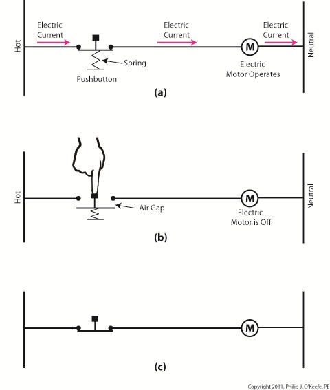
| Electric motors are everywhere, from driving the conveyor belts, tools, and machines found in factories, to putting our household appliances in motion. The first electric motors appeared in the 1820s. They were little more than lab experiments and curiosities then, as their useful potential had not yet been discovered. The first commercially successful electric motors didn’t appear until the early 1870s, and they could be found driving industrial devices such as pumps, blowers, and conveyor belts.
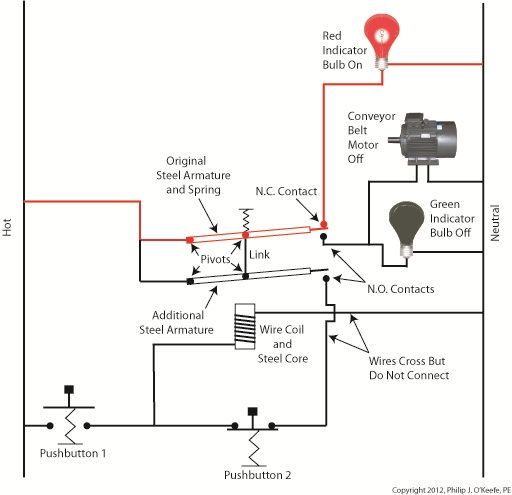
In our last blog we learned how a latched electric relay was unlatched at the push of a button, using red and green light bulbs to illustrate the control circuit. Now let’s see in Figure 1 how that circuit can be modified to include the control of an electric motor that drives, say, a conveyor belt inside a factory. Figure 1
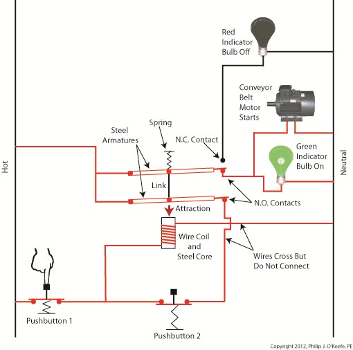
Again, red lines in the diagram indicate parts of the circuit where electrical current is flowing. The relay is in its normal state, as discussed in a previous article, so the N.O. contacts are open and the N.C. contact is closed. No electric current can flow through the conveyor motor in this state, so it isn’t operating. Our green indicator bulb also does not operate because it is part of this circuit. However current does flow through the red indicator bulb via the closed N.C. contact, causing the red bulb to light. The red and green bulbs are particularly useful as indicators of the action taking place in the electric relay circuit. They’re located in the conveyor control panel along with Buttons 1 and 2, and together they keep the conveyor belt operator informed as to what’s taking place on the line, such as, is the belt running or stopped? When the red bulb is lit the operator can tell at a glance that the conveyor is stopped. When the green bulb is lit the conveyor is running. So why not just take a look at the belt itself to see what’s happening? Sometimes that just isn’t possible. Control panels are often located in central control rooms within large factories, which makes it more efficient for operators to monitor and control all operating equipment from one place. When this is the case, the bulbs act as beacons of the activity taking place on the line. Now, let’s go to Figure 2 to see what happens when Button 1 is pushed. Figure 2
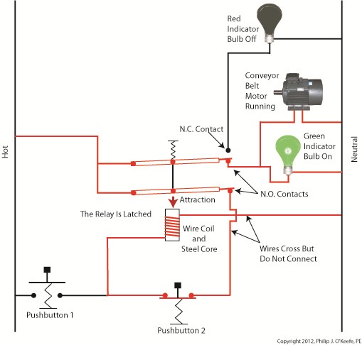
The relay’s wire coil becomes energized, causing the relay armatures to move. The N.C. contact opens and the N.O. contacts close, making the red indicator bulb go dark, the green indicator bulb to light, and the conveyor belt motor to start. With these conditions in place the conveyor belt starts up. Now, let’s look at Figure 3 to see what happens when we release Button 1. Figure 3
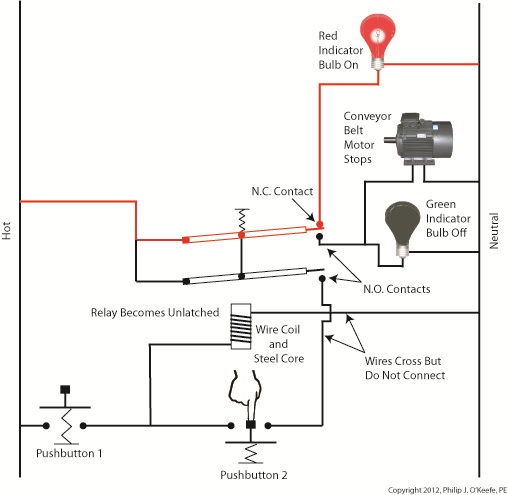
With Button 1 released the relay is said to be “latched” because current will continue to flow through the wire coil via one of the closed N.O. contacts. In this condition the red bulb remains unlit, the green bulb lit, and the conveyor motor continues to run without further human interaction. Now, let’s go to Figure 4 to see how we can stop the motor. Figure 4
When Button 2 is depressed current flow through the relay coil interrupted. The relay is said to be unlatched and it returns to its normal state where both N.O. contacts are open. With these conditions in place the conveyor motor stops, and the green indicator bulb goes dark, while the N.C. contact closes and the red indicator bulb lights. Since the relay is unlatched and current no longer flows through its wire coil, the motor remains stopped even after releasing Button 2. At this point we have a return to the conditions first presented in Figure 1. The ladder diagram shown in Figure 5 represents this circuit. Figure 5
Next time we’ll introduce safety elements to our circuit by introducing emergency buttons and motor overload switches. ____________________________________________ |
Posts Tagged ‘normally open’
Industrial Control Basics – Electric Motor Control
Sunday, February 19th, 2012Tags: blower, closed contact, control panel, control room, conveyor belt, electric current flow, electric motor, electric relay, engineering expert witness, equipment operator, factory, forensic engineer, indicator lamp, industrial control, ladder diagram, latched circuit, motor control, motor drive, N.C., N.O., normal state, normally closed, normally open, panel indicator, pump, push button, safety, start pushbutton, stop pushbutton
Posted in Engineering and Science, Expert Witness, Forensic Engineering, Innovation and Intellectual Property, Personal Injury, Product Liability, Professional Malpractice | Comments Off on Industrial Control Basics – Electric Motor Control
Industrial Control Basics – Latching Circuit
Sunday, January 29th, 2012| When I think of latches the first thing that comes to mind is my Uncle Jake’s outhouse and how I got stuck in it as a kid. Its door was outfitted with a rusty old latch that had a nasty habit of locking up when someone entered, and it would take a tricky set of raps and bangs to loosen. One day it was being particularly unresponsive to my repeated attempts to open it, and the scene became like something out of a horror movie. There was a lot of screaming.
When latches operate well, they’re indispensable. Let’s take our example circuit from last time a bit further by adding more components and wires. We’ll see how a latch can be applied to take the place of pressure exerted by an index finger. See Figure 1. Figure 1
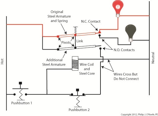
Our relay now contains an additional pivoting steel armature connected by a mechanical link to the original steel armature and spring. The relay still has one N.C. contact, but it now has two N.O. contacts. When the relay is in its normal state the spring holds both armatures away from the N.O. contacts so that no electric current will flow through them. One armature touches the N.C. contact, and this is the point at which current will flow between hot and neutral sides, lighting the red bulb. The parts of the circuit diagram with electric current flowing through them are denoted by red lines. Figure 1 reveals that there are now two pushbuttons instead of one. Now let’s go to Figure 2 to see what happens when someone presses on Button 1. Figure 2
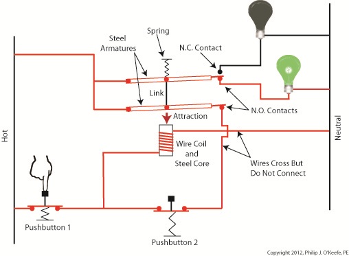
Again, the parts of the circuit diagram with current flowing through them are denoted by red lines. From this diagram you can see that when Button 1 is depressed, current flows through the wire coil, making it and its steel core magnetic. This electromagnet in turn attracts both steel armatures in our relay, causing them to pivot and touch their respective N.O. contacts. Electric current now flows between hot and neutral sides, lighting up the green bulb. Current no longer flows through the N.C. contact and the red bulb, making it go dark. If you look closely at Figure 2, you’ll notice that current can flow to the wire coil along two paths, either that of Button 1 or Button 2. It will also flow through both N.O. contact points, as well as the additional armature. So how is this scenario different from last week’s blog discussion? That becomes evident in Figure 3, when Button 1 is no longer depressed. Figure 3
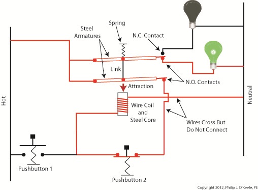
In Figure 3 Button 1 is not depressed, and electric current does not flow through it. The red bulb remains dark, and the green bulb lit. How can this state exist without the human intervention of a finger depressing the button? Because although one path for current flow was broken by releasing Button 1, the other path through Button 2 remains intact, allowing current to continue to flow through the wire coil. This situation exists because Button 2’s path is “latched.” Latching results in the relay’s wire coil keeping itself energized by maintaining armature contact at the N.O. contact points, even after Button 1 is released. When in the latched state, the magnetic attraction maintained by the wire coil and steel core won’t allow the armature to release from the N.O. contacts. This keeps current flowing through the wire coil and on to the green bulb. Under these conditions the relay will remain latched. But, just like my Uncle’s outhouse door, the relay can be unlatched if you know the trick to it. Relays may be latched or unlatched, and next week we’ll see how Button 2 comes into play to create an unlatched condition in which the green bulb is dark and the red bulb lit. We’ll also see how it is all represented in a ladder diagram. ____________________________________________ |
Tags: armature, automatic controls, controls engineer, electric current, electric relay, electrical contacts, electromagnet, engineering expert witness, forensic engineer, hot, industrial control, ladder diagram, latched relay, N.C. contact, N.O. contact, NC contact, neutral, NO contact, normal state, normally closed, normally open, pushbutton, relay, relay ladder logic, unlatched relay, wire, wire coil
Posted in Engineering and Science, Expert Witness, Forensic Engineering, Innovation and Intellectual Property, Personal Injury, Product Liability, Professional Malpractice | Comments Off on Industrial Control Basics – Latching Circuit
Industrial Control Basics – Electric Relay Ladder Diagram
Sunday, January 22nd, 2012| My daughter will be studying for her driver’s license exam soon, and I can already hear the questions starting. “What does that sign mean? Why does this sign mean construction is ahead?” Symbols are an important part of our everyday lives, and in order to pass her test she’s going to become familiar with dozens of them that line our highways.
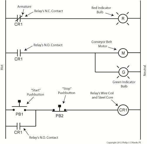
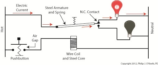
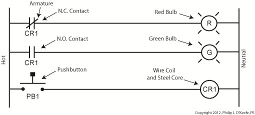
Just as a triangle on the highway is a symbol for “caution,” industrial control systems employ a variety of symbols in their diagrams. The pictures are shorthand for words. They simplify the message, just as hieroglyphics did for our early ancestors who had not yet mastered the ability to write. Ladder diagrams and the abstract symbols used in them are unique to industrial control systems, and they result in faster, clearer interpretations of how the system operates. Last week we analyzed an electric circuit to see what happens when we put a relay to use within a basic industrial control system, as found in Figure 1. Figure 1Now let’s see how it looks in an even simpler form, the three-rung ladder diagram shown in Figure 2. Figure 2In industrial control terminology the electric relays shown in ladder diagrams are often called “control relays,” denoted as CR. Since a ladder diagram can typically include many different control relays, they are numbered to avoid confusion. The relay shown in Figure 2 has been named “CR1.” Our ladder diagram contains a number of symbols. The symbol on the top rung which looks like two parallel vertical lines with a diagonal line bridging the gap between them represents the N.C. contact. This symbol’s vertical lines represent an air gap in the N.C. contact, the diagonal line is the relay armature which performs the function of bridging/closing the air gap. This rung of the ladder diagram represents the contact when the relay is in its normal state. In the middle ladder rung the N.O. contact symbol looks like two parallel vertical lines separated by a gap. There is no diagonal line running through it since the relay armature doesn’t touch the N.O. contact when this particular relay is in its normal state. The wire coil and steel core of this relay are represented by a circle on the bottom ladder rung. The contact and coil symbols on all three rungs are labeled “CR1” to make it clear that they are part of the same control relay. Other symbols within Figure 2 represent the red and green bulbs we have become familiar with from our initial illustration. They are depicted as circles, R for red and G for green, with symbolic light rays around them. The pushbutton, PB1, is represented as we have discussed in previous articles on ladder diagrams. Just as road sign symbols are faster than sentences for drivers speeding down a highway to interpret, ladder diagrams are faster than customary illustrations for busy workers to interpret. Next time we’ll expand on our electric relay by introducing latching components into the control system that will allow for a greater degree of automation. ____________________________________________ |
Tags: armature, automation engineer, bulb, contact, control relay, controls engineer, CR, electric relay, electrical contact, engineering expert witness, forensic engineer, hot, industrial automation, industrial control, ladder diagram, ladder diagram symbol, ladder logic, N.C. contact, N.O. contact, NC contact, neutral, NO contact, normal state, normally closed, normally open, pushbutton, relay, rung, steel core, wire coil
Posted in Engineering and Science, Expert Witness, Forensic Engineering, Innovation and Intellectual Property, Personal Injury, Product Liability, Professional Malpractice | 2 Comments »
Industrial Control Basics – Electric Relay Operation
Monday, January 9th, 2012| It’s a dark and stormy night and you’ve come to the proverbial fork in the road. The plot is about to take a twist as you’re forced to make a decision in this either/or scenario. As we’ll see in this article, an electric relay operates in much the same manner, although choices will be made in a forced mechanical environment, not a cerebral one.
When we discussed basic electric relays last week we talked about their resting in a so-called “normal state,” so designated by industrial control parlance. It’s the state in which no electric current is flowing through its wire coil, the coil being one of the major devices within a relay assembly. Using Figure 3 of my previous article as a general reference, in this normal state a relaxed spring keeps the armature touching the N.C. switch contact. While in this state, a continuous conductive path is created for electricity through to the N.C. point. It originates from the wire on the left side, which leads to the armature pivot point, travels through the armature and N.C. contact points, and finally dispenses through the wire at the right leading from the N.C. contact. Now let’s look at an alternate scenario, when current is made to flow through the coil. See Figure l, below. Figure 1Figure 1 shows the path of electric current as it flows through the wire coil, causing the coil and the steel core to which it’s attached to become magnetized. This magnetization is strong, attracting the steel armature and pulling it towards the steel core, thus overcoming the spring’s tension and its natural tendency to rest in a tension-free state. The magnetic attraction causes the armature to rotate about the pivot point until it comes to rest against the N.O. contact, thus creating an electrical path en route to the N.O. wire, on its way to whatever device it’s meant to energize. As long as current flows through the wire coil, its electromagnetic nature will attract the armature to it and contact will be maintained with the N.O. juncture. When current is made to flow through the wire coil, an air gap is created between the armature and the N.C. contact, and this prevents the flow of electric current through the N.C. contact area. Current is forced to follow the path to the N.O. contact only, effectively cutting off any other choice or fork in the road as to electrical path that may be followed. We can see that the main task of an electric relay is to switch current between two possible paths within a circuit, thereby directing its flow to one or the other. Next time we’ll examine a simple industrial control system and see how an electric relay can be engaged with the help of a pushbutton. ____________________________________________ |
Tags: armature, coil, control relay, control system, current flow, electric current, electric relay, electrical path, electrical relay, electrical switch, electricity, electromagnetic, engineering expert witness, forensic engineering, industrial control, magnetic attraction, N.C., N.C. contact, N.O., N.O. contact, normal state, normally closed, normally open, pushbutton, relay, relay ladder logic, spring, steel core, switch, switch contact, switching current, wire coil
Posted in Engineering and Science, Expert Witness, Forensic Engineering, Innovation and Intellectual Property, Personal Injury, Product Liability, Professional Malpractice | 1 Comment »
Industrial Control Basics – Introduction to Electric Relays
Tuesday, January 3rd, 2012| I’ve always considered science to be cool. Back in the 5th grade I remember fondly leafing through my science textbook, eagerly anticipating our class performing the experiments, but we never did. For some reason my teacher never took the time to demonstrate any. Undeterred, I proceeded on my own.
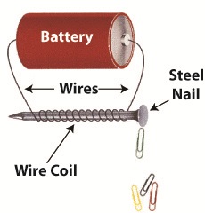
I remember one experiment particularly well where I took a big steel nail and coiled wire around it. When I hooked a battery up to the wires, as shown in Figure 1 below, electric current flowed from the battery through the wire coil. This set up a magnetic field in the steel nail, thereby creating an electromagnet. My electromagnet was strong enough to pick up paper clips, and I took great pleasure in repeatedly picking them up, then watching them unattach and fall quickly away when the wires were disconnected from the battery. Figure 1
Little did I know then that the electromagnet I had created was similar to an important part found within electrical relays used in many industrial control systems. An example of one of these relays is shown in Figure 2. Figure 2
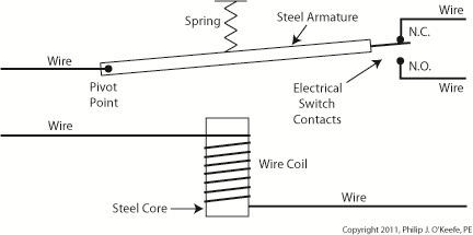
So, what’s in the little plastic cube? Well, a relay is basically an electric switch, similar to the ones we’ve discussed in the past few weeks, the major difference being that it is not operated directly by human hands. Rather, it’s operated by an electromagnet. Let’s see how this works by examining a basic electrical relay, as shown in Figure 3. Figure 3
The diagram in Figure 3 shows a basic electric relay constructed of a steel core with a wire coil wrapped around it, similar to the electromagnet I constructed in my 5th grade experiment. If the coil’s wires are not hooked up to a power source, a battery for example, no electric current will flow through it. When there is no current the coil and steel core are not magnetic. For purposes of our illustration and in accordance with industrial control parlance, this is said to be this relay’s “normal state.” Next to the steel core there is a movable steel armature, a kind of lever, which is attached to a spring. On one end of the armature is a pivot point, on the other end is a set of electrical switch contacts. When the relay is in its normal state, the spring’s tension holds the armature against the “normally closed,” or N.C., contact. If electric current is applied to the wire leading to the pivot point on the armature while in this state, it will be caused to flow on a continuous path through the armature and the N.C. contact, then out through the wire leading from the N.C. contact. In our illustration, since the armature does not touch the N.O. contact, an air gap is created that prevents electric current from traveling through the contact from the armature. Next week we’ll see how these parts come into play within a relay when electric current flows through the coil, turning it into an electromagnet. ____________________________________________ |
Tags: armature, control system, electric current, electric relay, electrical switch contacts, electromagnet, electromechanical relay, engineering expert witness, forensic engineer, industrial control, magnet, magnetic steel core, normal state, normally closed, normally open, power, relay, relay logic, spring, steel core, switch, switch contact, wire, wire coil
Posted in Engineering and Science, Expert Witness, Forensic Engineering, Innovation and Intellectual Property, Personal Injury, Product Liability, Professional Malpractice | Comments Off on Industrial Control Basics – Introduction to Electric Relays
Industrial Control Basics – Pushbuttons
Monday, December 26th, 2011Tags: control system, current flow, electric motor, electrical circuit, engineering expert witness, forensic engineer, hot, industrial control, ladder diagram, machine control, mechanized equipment, motor control, neutral, normally closed, normally open, pushbutton, relay, spring, switch
Posted in Engineering and Science, Expert Witness, Forensic Engineering, Innovation and Intellectual Property, Personal Injury, Product Liability, Professional Malpractice | Comments Off on Industrial Control Basics – Pushbuttons
