|
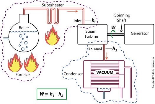
Last time we learned how enthalpy is used to measure heat energy contained in the steam inside a power plant. The higher the steam pressure, the higher the enthalpy, and vice versa, and we touched upon the concept of work, or the potential for a useful outcome of a process. Today we’ll see how to get the maximum work out of a steam turbine by attaching a condenser at the point of its exhaust and making the most of the vacuum that exists within its condenser. Let’s revisit the equation introduced last time, which allows us to determine the amount of useful work output: W = h1 – h2 Applied to a power plant’s water-to-steam cycle, enthalpy h1 is solely dependent on the pressure and temperature of steam entering the turbine from the boiler and superheater, as contained within the purple dashed line in the diagram below. As for enthalpy h2, it’s solely dependent on the pressure and temperature of steam within the condenser portion of the water-to-steam cycle, as shown by the blue dashed circle of the diagram. Next week we’ll see how the condenser, and more specifically the vacuum inside of it, sets the platform for increased energy production, a/k/a work.
________________________________________ |
Posts Tagged ‘power plant training’
Enthalpy and the Potential for More Work
Monday, November 18th, 2013Enthalpy and Steam Turbines
Thursday, November 14th, 2013|
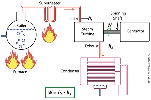
Last time we learned how the formation of condensate within a power plant’s turbine results in a vacuum being created. This vacuum plays a key role in increasing steam turbine efficiency because it affects a property known as enthalpy, a term used to denote total heat energy contained within a substance. For the purposes of our discussion, that would be the heat energy contained within steam which flows through the turbine in a power plant. The term enthalpy was first introduced by scientists within the context of the science of thermodynamics sometime in the early 20th Century. As discussed in a previous blog article, thermodynamics is the science that deals with heat and work present within processes. Enthalpy is a key factor in thermodynamics, and is commonly represented in engineering calculations by the letter h and denoted as, h = u + Pv where u is the internal energy of a substance, let’s say steam; P is the pressure acting upon a specific volume, v, of the steam; and P and v are multiplied together. Pressure is force per unit area and is measured in psi, pounds per square inch. For the purposes of our discussion, it’s the amount of pressure that steam places on pipes containing it. Looking at the equation above, simple math tells us that if we increase the pressure, P, the result will be an increase in enthalpy h. If we decrease P, the result will be a decrease in h. Now, let’s see why this property is important with regard to the operation of a steam turbine. When it comes to steam turbines, thermodynamics tells us that the amount of work they perform is proportional to the difference between the enthalpy of the steam entering the turbine and the enthalpy of the steam at the turbine’s exhaust. What is meant by work is the act of driving the electrical generator, which in turn provides electric power. In other words, the work leads to a useful outcome. This relationship is represented by the following equation, W = h1 – h2 In terms of the illustration below, W stands for work, or potential for useful outcome of the turbine/generator process in the form of electricity, h1 is the enthalpy of the steam entering the inlet of the turbine from the superheater, and h2 is the enthalpy of the steam leaving at the turbine exhaust. We’ll discuss the importance of enthalpy in more detail next week, when we’ll apply the concept to the work output of a steam turbine.
________________________________________ |
Vacuum in a Power Plant Condenser
Tuesday, November 5th, 2013|
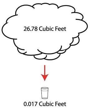
Last time we discussed the key functions of the make-up valve in the power plant water-to-steam cycle. Today we’re going to talk about a vacuum. No, not the kind you use around the house, the kind that’s created by the condenser inside a power plant. As discussed previously, the condenser is a piece of equipment that turns turbine exhaust steam back into water. The water that’s formed during this process is known as condensate, and its density is higher than that of the steam it shares space with inside the condenser. That difference in density is what creates the vacuum inside the condenser vessel. Put another way, the increase in density along with the condenser’s airtight design prevent air from rushing in from outside to occupy any of the space inside the condenser, a desirable condition from an efficiency standpoint. But to understand how all this works we’ll first have to gain an understanding of what is meant by density. A textbook would define it as the mass of a substance divided by the amount of space that that substance occupies. Let’s take steam and water for example. One pound of steam at 212°F forms a vapor cloud that occupies 26.78 cubic feet of space. If we condensed that pound of steam back into water at the same temperature, it would just about fit into a 16 ounce glass and occupy a mere 0.017 cubic feet. The huge difference in their volumes is due to the fact that steam contains more than five times the heat energy that unheated water does. That energy makes the molecules in a cloud of steam more active, causing them to collide against each other with great force, spread apart, and occupy a larger space. If you’re wondering what change in density has to do with vacuum in the condenser, allow me to offer an analogy. Ever canned any produce, like tomatoes, in glass jars to over-winter? Not likely, as this once common survival tactic has nearly become a lost art. But the vacuum created inside the condenser is much like the vacuum created within a mason jar during canning. Inside the glass mason jar, a small space is intentionally left between the tomatoes and lid. During the process of boiling, or heat sterilization, this space fills with steam. Then during cooling the trapped steam condenses into water. This condensation creates the vacuum that sucks down on the jar’s lid, giving it an airtight seal, a condition which won’t allow bacteria to grow on our canned foods. You see, like us bacteria need oxygen to live, but thanks to the vacuum inside our cooked mason jar no air containing oxygen will remain inside to harbor it. Next time we’ll continue our discussion on vacuum to see how it’s used to increase a steam turbine’s efficiency.
________________________________________ |
The Make-up Valve in the Power Plant Steam to Water Cycle
Monday, October 28th, 2013|
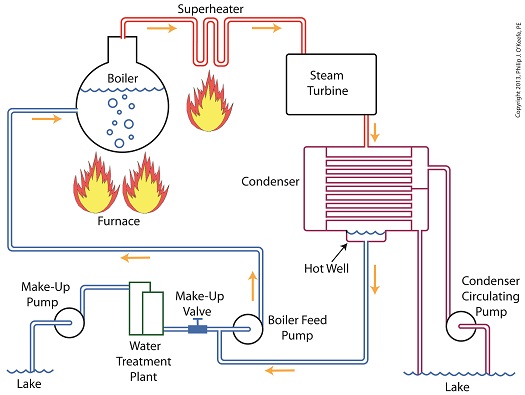
Last time we learned how the condenser recycles steam from the turbine exhaust by condensing it back into water for its reuse within the power plant steam-water cycle. This water is known as condensate, and after leaving the boiler feed pump at high pressure, it’s known as boiler feed water. Today we’ll introduce a special valve into the system, whose job it is to perform the important function of compensating for lost water. It’s known as the make-up valve. The illustration shows the flow of steam and water within the cycle. Tracing the path of orange arrows will reveal it as a closed system. Under ideal operating conditions recycled condensate from the condenser would provide enough water to keep the boiler indefinitely supplied. In reality water and steam leaks are a chronic problem within power plants, even when well maintained. Leaks typically occur due to worn parts on equipment, a condition which is commonly present due to the demanding operating conditions they must endure. First, there is the strain of continuous operation, then there are the high temperatures, typically greater than 1000°F, and high pressures that pipes, valves, pumps, and the boiler itself must endure. We’re talking about pressure higher than 2000 psi, that is, pounds per square inch. As a result, water levels within the boiler must periodically be replenished. While tracing the arrows through the diagram, you would have come across the new make-up valve under discussion. It’s located on the pipe leading from the power plant’s water treatment system to the boiler feed pump. It’s normally kept closed, except under two circumstances, when the boiler is initially filled at startup, or when water replenishment needs to take place. Due to water loss and difficult operating conditions, maintenance within the water-to-steam system of a power plant is a never ending task. There are miles of pipe connected to hundreds of pieces of equipment, all of which are distributed through a huge power plant structure. So the reality is that power plants operate with a continuous eye on leakage. To contend with the leaks, human intervention is often required in the way of a boiler operator. Their job is to manually open the make-up valve to admit a fresh supply of water from the treatment plant to the boiler via the boiler feed pump. Once the system’s water requirements are replenished, the valve is once again closed. Next time we’ll continue this series by discussing how the condenser enables the steam turbine to run more efficiently by creating a vacuum at the turbine’s exhaust.
________________________________________ |
Superheater Construction and Function
Sunday, September 15th, 2013|
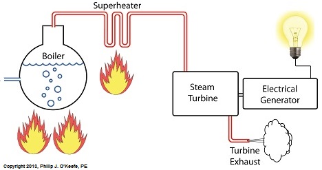
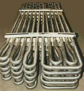
Power plants produce electrical energy for consumers to use, whether at home or for business, that’s obvious enough, but did you know that in order to produce that electrical energy they must first be supplied with heat energy? The heat energy that power plants crave comes from a fuel source, such as coal, oil, or natural gas, by way of a burning process. Once the heat energy is released from the coal through burning, it’s transported into a steam turbine by way of superheated steam, which is supplied to it by a piece of equipment named, appropriately enough, a superheater. So what is a superheater and how does it function? Take a look at the illustration below. The superheater looks like a W. It’s actually a cascading array of bent steam pipe, situated above a source of open flames which are produced by the burning of a fuel source. A photo of an actual superheater is shown below. So how many bends are in a superheater? Enough to fill the needs of the particular power plant it is supplying energy to. Since all power plants are designed differently, we’ll keep things in general terms. The many bends in the superheater’s pipes form a circuitous path for steam to flow as it follows a path from the boiler to the steam turbine. The superheater’s unique construction gives the steam flowing through it maximum exposure to heat. In other words, the bends increase the time it takes for the steam to flow through the superheater. The more bends that are present, the longer the steam will be exposed to the flame’s heat energy, and the longer that exposure, the more heat energy that is absorbed by the steam. Superheating routinely results in temperatures in excess of 1000°F. This superheated steam is laden with abundant heat energy which will keep the steam turbine spinning and the generator operating. The net result is millions of watts of electrical power. As we learned in a previous blog, the superheater is designed to provide the turbine with sensible heat energy to prevent steam from completely desuperheating, which would result in dangerous condensation inside the turbine. The newly added superheater is a major improvement to a power plant’s water-to-steam cycle, but there’s still plenty of waste and inefficiency in the system, which we’ll discuss next week.
________________________________________ |
Desuperheating in the Steam Turbine
Monday, September 2nd, 2013|
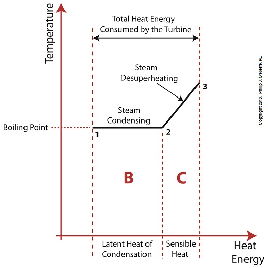
Last time we learned that the addition of a superheater to the electric utility power plant steam cycle provides a ready supply of high temperature steam, laden with heat energy, to the turbine, which in turn powers the generator. But this isn’t its only job. One of the superheater’s most important functions is to regulate the ongoing process of desuperheating that takes place as the turbine consumes heat energy. To understand this, let’s see what takes place if the superheater were to be removed from its position between the boiler and turbine. Figure 1
Without the superheater, the only available remaining source of sensible heat energy to the turbine would come from the meager amount present in phase C steam as shown in Figure 1. If you’ll recall from a past blog, the sensible heat energy contained in superheated steam is the best source of energy for a steam turbine, because it’s able to keep it operating most efficiently. As the turbine consumes the heat energy in phase C, starting at point 3 and continuing to point 2, the steam it’s consuming is in the process of desuperheating, as evidenced by the downward slope between the two points. Desuperheating is an engineering term which means that as sensible heat energy is removed from the steam due to its use by the turbine, there will be a resulting drop in steam temperature. And if this process were to continue without the compensatory function provided by the addition of a superheater to the steam cycle, the steam’s temperature would eventually return to mere boiling point, at point 2. This is an undesirable thing. With the steam’s temperature at boiling point, the only remaining source of heat energy to the turbine is the latent heat energy of phase B. This heat energy will lead to an undesirable circumstance for the operation of our power hungry turbine as we will see next week. ________________________________________ |
Heat Energy Within the Power Plant— Water and Steam Cycle, Part 2
Wednesday, August 14th, 2013|
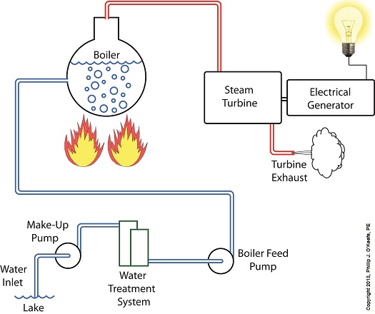
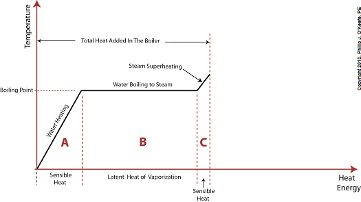
Last time we learned that electric utility power plants must have water treatment systems in place to remove contaminants from incoming feed water before it can be used. This clarified water is then fed to a boiler by the boiler feed pump as shown below. As it stands this setup will work to provide electricity, however in this state it’s both inefficient and wasteful. We’ll see why in a minute. Boilers, as their name implies, do a great job of heating water to boiling point to produce steam. They do this by adding the heat energy produced by burning fuel, such as coal, to water, then steam. We learned in earlier blogs in this series that the energy used to heat water to boiling point temperature is known as sensible heat, whereas the heat energy used to produce steam is known as latent heat. The key distinction between these two phases is that during sensible heating there is a rise in temperature, during latent heating there is not. For a review on this, see this blog article. When water starts to heat inside the boiler, sensible heat energy is said to be added. This is represented by phase A of the graph below. During A, heat energy will raise the temperature of the water to boiling point. As the water continues to boil in phase B, water is transforming into steam. During this phase latent heat energy is said to be added, and the temperature will remain at boiling point. In phase C something new takes place. The temperature rises beyond boiling point and only steam is present. This is known as superheated steam. For example, if the boiler pressure is at 1,500 pounds per square inch, steam becomes superheated at temperatures greater than 600°F. Unfortunately, boilers alone do a poor job of superheating steam, that is, continuing to raise the temperature of the steam present in phase C. This is evident by the fact that phase C is quite small in comparison to phases A and B before it. This inefficiency in producing ample amounts of superheated steam results in a small amount of useful energy being provided to the turbine down the line, which is bad, because steam turbines require exclusively superheated steam to run the generator. Next time we’ll see how to provide our steam turbine with more of what it needs to run the generator, more superheated steam. ___________________________________________
|
Coal Power Plant Fundamentals – The Generator
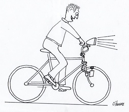
Monday, March 7th, 2011| When I was a kid I remember how cool it was to have a headlight on my bike. Unlike the headlights that the other kids had, mine was not powered with flashlight batteries. The power came from a little gadget with a small wheel that rode on the front tire. As I pedaled along, the tire’s spinning caused the small wheel to spin, and voila, the headlight bulb came to life. Little did I know that this gadget was a simple form of electrical generator, and of course I was oblivious to the fact that a similar device, albeit on a much larger scale, was being used at a nearby power plant to send electricity to my home.
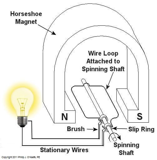
Over the last few weeks we learned how a coal fired power plant transforms chemical energy stored in coal into heat energy and then into mechanical energy which enables a steam turbine shaft to spin. We’ll now turn our attention to the electrical generator. It’s responsible for performing the last step in the energy conversion process, that is, it converts mechanical energy from the steam turbine into the desired end product, electrical energy for our use. It represents the culmination in energy’s journey through the power plant, the process by which energy contained in a lump of coal is transformed into electricity. To show how this final energy conversion process works, let’s look at Figure 1, a simplified illustration of an electrical generator. Figure 1 – A Basic Electrical Generator You’ll note that the generator in our illustration has a shaft with a loop of wire attached to it. When the shaft spins, so does the loop. The shaft and wire loop are placed between the north (N) and south (S) poles of a horseshoe magnet. It’s a permanent magnet, so it always has invisible lines of magnetic flux traveling between its two poles. These magnetic lines of flux are the same type as the ones created by kids’ magnets, when they play with watching paperclips jump up to meet the magnet. The properties of magnets are not completely understood, even to adults who work with them every day. And what could be more mysterious than the fact that as the shaft and wire loop spin through the lines of magnetic flux in the generator, an electric current is produced in the wire loop. Now, this current that’s flowing through the spinning wire loop is of no use if we can’t channel it out of the generator. The wire loop is spinning vigorously, so you can’t directly connect the ends of the loop to stationary wires. A special treatment is required. Each end of the loop is connected to a slip ring. A part called a “brush” presses against each slip ring to make electrical contact. The electrical current then flows from the loop through the spinning slip rings, through the brushes, and into the stationary wires. So, if, for example, a light bulb is connected to the other end of the stationary wires, this completes an electric circuit through which current can flow. The light bulb will glow as long as the generator shaft keeps spinning and the wire loop keeps passing through the magnetic lines of flux from the magnet. So we see that the key to the whole energy conversion process is to have movement between magnetic lines of flux and a loop of wire. As long as this movement occurs, the electricity will flow. This basic principle is the same in a coal fired power plant, but the electrical generator is far more complicated in construction and operation than shown here. My Coal Power Plant Fundamentals seminar goes into far greater detail on this and other aspects of electricity generation, but what I have shared with you above will give you a basic understanding of how they operate. That concludes our journal with coal through the power plant. This series of blogs has, you will remember, presented a simplified version of the complex material presented in my teaching seminars. Next week we’ll branch off, taking a look at why electrical wires come in different thicknesses. _____________________________________________
|
Coal Power Plant Fundamentals – Feeding The Furnace
Sunday, February 6th, 2011| Today we’ll continue our discussion of coal’s journey through a power plant. Keep in mind that the material presented in this series of blogs is meant to be a primer. It is a simplification of what actually goes on. My training seminars go into much more depth.
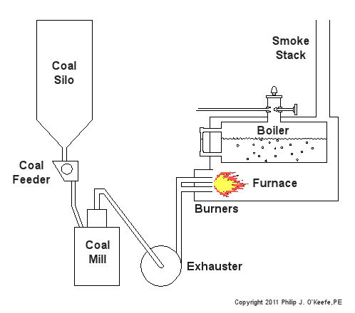
Now imagine a five course meal spread out on the table before you. You load up your plate and pack a forkful of food into your mouth. You instinctively chew, getting the digestive process underway and making it easier to swallow. Power plants approach their consumption of coal in much the same way. Last time we talked about handling the coal and filling up silos for short term storage within the power plant building. The coal silo is analogous to a dinner plate, and the furnace, which heats up the boiler water to make steam for the turbine, acts very much like a diner’s stomach. As for the fork and your teeth, there are a couple of machines within power plants which mimic their behavior. They’re called the coal feeder and coal mill. The coal feeder does as its name implies, it systematically feeds a measured amount of coal to the coal mill. The coal mill, also known as a pulverizer, then grinds the coal to make it easier for the furnace to burn it. Let’s take a look at Figure 1 below. At the top of the configuration is the coal silo, which is fully open at the bottom. Gravity draws the coal within the silo downward, facilitating the coal’s dropping through the opening into a chute, on its way to the coal feeder. The coal from the silo spills into little buckets on a wheel within the feeder, and as the wheel turns, the coal spills out and falls down into another chute leading to the mill. Figure 1 – Feeding Coal To A Power Plant Furnace Now you could have the coal spill down a chute directly from the silo into the mill, bypassing the coal feeder entirely, but that’s really not a good idea. Just think how difficult it would be to chew if you tried to stuff an entire plate of food into your mouth at once. Just as your mouth requires to be fed in mouth-sized amounts, the coal mill must be fed coal in a size that it can handle. It’s the job of the spinning wheel inside the coal feeder to keep coal flowing in measured amounts to the mill. You see, the wheel is attached to a variable speed motor, and depending on how quickly the furnace needs to be fed, the wheel will either turn faster or slower. Once inside the mill, the coal is ground up before moving on to the furnace. The coal mill contains massive steel parts capable of pulverizing chunks of coal into a fine black powder. This pulverized coal is then propelled by means of an exhauster towards the burners. The exhauster sits next to the coal mill and both are often driven by the same electric motor. The exhauster is connected to the top of the mill by a pipe, and another pipe connects the exhauster to burners on the furnace. The exhauster acts like a big vacuum cleaner, sucking coal powder out of the mill, then blowing it through pipes leading to the burners. Finally, the powder ignites within the furnace, heating the water inside the boiler. Next time we’ll learn about the combustion process in the power plant furnace. _____________________________________________ |
