| If you’ve ever read a book to a small child on the subject of food or digestion, you’ve probably come across the analogy that our stomachs are like a furnace and our digestive system much like an engine. We explain to the youngster that what we eat is important, because our body needs the right fuel in order to operate properly. If little Susie or Danny insisted on eating only candy day after day, their bodies would become weak and sick.
In much the same way a coal power plant is like a living organism, eating fuel in order to function. But instead of meats and vegetables, it eats coal, and the coal handling department of a power plant acts as a dinner table. It’s where the food is placed and prepared before it enters the diner’s mouth. The coal our power plants consume comes from one of two places, underground mines or strip mines. It all depends on the particular geology of the area from which the coal is harvested. According to the US Energy Information Administration, underground mines are more common in the eastern United States, while strip mines are more common in the western states. The coal from underground mines is excavated by means of shafts and tunnels which are dug deep beneath the earth’s surface in order to provide access to the buried coal deposits. In strip mines the deposits are just below the surface, so the topsoil is merely stripped away with heavy earthmoving machinery, like bulldozers, to reveal the coal. In both types of mining activity excavating machines and conveyors are required to remove the coal from the mine so it can be loaded for shipment to its ultimate destination. Once harvested, coal is shipped to power plants primarily by train, river barge, or ship. Its journey can cover thousands of miles. It culminates in delivery to a power plant, where it is unloaded by means of a huge piece of machinery called a rotary dumper. This machine is capable of grabbing onto 100 ton railcars and turning them upside down. The coal spills into a large collection hopper positioned next to the railroad track. If the coal has found its way to a plant located near a waterway, that means of transport was most likely have been made by flat barge or ship. In this case a large crane with a clamshell bucket is used for unloading. The crane drops its bucket into a pile of coal located within the ship’s hold, takes out a large bite, then hoists and dumps its contents into a large collection hopper next to the crane. To get an idea of how coal flows within the coal handling system of a power plant, let’s refer to the flow chart in Figure 1.
Figure 1 – Schematic Diagram of the Coal Handling System Collection hoppers and have slanted bottoms which allow coal to easily spill out onto a conveyor belt. Within the plant coal is transported by means of conveyors into what’s known as a “breaker building.” This building lives up to its name because it contains a very large machine whose job it is to break the chunks of raw coal that have been harvested from mines into smaller chunks which the boiler can work with. Once broken down, the coal will go to one of two places, either directly into silos or coal bunkers in the power plant building for short term storage, or into an outside storage pile, usually a prominent feature of a power plant due to its formidable size. The coal pile can be several stories tall and much larger than a football field. It acts as a reserve supply should the regular delivery of coal be interrupted by labor strike, natural disaster, or equipment failure. When necessary, the coal is removed from the pile and sent into the plant to fill the coal silos. Coal from the silos is used to feed the power plant boilers. Next week we’ll continue to follow coal’s journey, on its way to arguably one of the most important pieces of equipment in a power plant, the boiler. _____________________________________________
|
Posts Tagged ‘railroad track’


Regenerative Brakes
Sunday, June 13th, 2010|
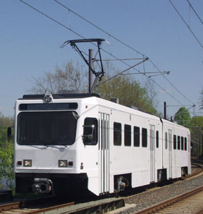
Have you ever been stranded on a subway car? The lights flickered wildly, then the odd humming sounds all came to an abrupt stop, and you sat there exchanging uncomfortable glances with your fellow passengers? “Hey, get this thing going! I’ve got an appointment to make!” someone shouts at the driver, sequestered in his cab. The trouble is, he, like the rest of the passengers, is equally helpless in this situation. You see, streetcars, subway cars, and light rail cars are all forms of electric railway cars, and when their source of electricity goes out, so do they. They’re similar to the diesel-electric locomotive we looked at last week because they use electric traction motors for propulsion, meaning to move forward. But their difference lies in the fact that electric rail cars don’t carry their own source of power and are entirely reliant on an external source, an electrical substation. See Figure 1 below.
Figure 1 – Electric Railway Car Propulsion System This substation performs the task of taking the power provided by an electric utility power plant and converting it into a form of power that the electric rail car can use to operate its traction motors. The two are connected via a trolley wire and the two rails that the car runs on. The railway car has a spring-loaded arm called a pantograph on its roof that touches the trolley wire, allowing electrical current to flow into a speed control system housed under the car. This speed control system performs the task of varying the flow of electrical current to the traction motors, enabling the car to move, before it eventually exits the motor through its wheels, then back to the substation where it originated, thus completing an electrical circuit. Many newer electric railway cars couple a regenerative braking system with a mechanical one. Their operation is similar in nature to a dynamic braking system where the traction motors are turned into generators. The difference is that with regenerative braking systems the current from the traction motors is sent to the trolley wire through the pantograph as shown in Figure 2 below.
Figure 2 – An Electric Railway Car Using Regenerative Brakes This diagram shows the railcar generating electricity, but it may not be so obvious how its motion is made to slow down, after all, we see no resistor grids like we did in last week’s illustration of a dynamic braking system. So how does it stop? The trick here is that there are other cars running on the rail line at the same time which are using electrical current to move forward. So what does this have to do with stopping it you ask? Let’s take a look at Figure 3 for clarification. Figure 3 – How Regenerative Brakes Help Save Power In this illustration we see that as Car A goes downhill and the operator applies the brakes, the regenerative brake will be caused to start pumping electrical current into the trolley wire. Now, if Car B is on the same rail line going up the other side of the hill, it will need power to climb that hill, and it will need to draw that power from the trolley wire by way of its pantograph. But instead of drawing all its electrical current from the substation, Car B will first draw off the current produced by nearby Car A, and only then will it draw the remainder of its power requirements from the substation. During this braking process the kinetic energy in Car A is converted into electrical energy by its traction motors. Then Car B uses its own traction motors to convert the electrical energy drawn from Car A into mechanical energy, enabling it to climb the hill. Car B has effectively robbed Car A of its energy, so Car A slows down. As we discovered last week during our discussion of dynamic brakes, regenerative brakes become ineffective below a certain minimum speed. This is the reason that electric rail cars need mechanical brakes to complete the job of stopping. We see that the regenerative braking process is actually quite green. It allows for electrical energy that would normally be wasted as heat energy escaping into the atmosphere to be converted into useful energy, taking a significant chunk out of the demand for new energy off of substations. It also helps the electric railway to save money when it comes time to paying the electric bills. You may have noticed a copyright symbol and my name included in this week’s illustrations. That’s because it has recently come to my attention that many of my readers are unaware that I am the CAD (Computer Aided Design) artist who creates the illustrations featured in most of my blogs. CAD is a useful tool in explaining difficult technical subject matter, which is precisely why I use it so often. Next week we’ll explore in more depth the benefits of using this tool.
_____________________________________________
|


