|
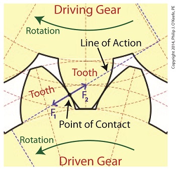
Inertia. It’s the force that keeps us in bed after the alarm has rung. It seems to have a life of its own, and today we’ll see how it comes into play in keeping other stationary objects at rest. Last time we identified a specific point of contact between spur gear teeth in a gear train and introduced the opposing forces, F1 and F 2, generated there. Today we’ll see what these forces represent, identifying one of them as inertia. So where do these forces come from? They’re forces generated by different means that converge at the same point of contact, the point at which gear teeth mesh. They follow a very specific geometric path to meet there, an imaginary straight line referred to as the line of action. F1 is always generated by a source of mechanical energy. In our locomotive example introduced earlier in this blog series that source is an electric traction motor, upon which a driving gear is mounted. When the motor is energized, a driving force F1 is generated, which causes gear teeth on the driving gear to push against gear teeth of the driven gear. Force F2 is not as straightforward to understand, because it’s not generated by a motor. Instead, it’s the resisting force that the weight of a stationary object poses against its being moved from an at-rest position, known as inertia. The heavier the object, the more inertia it presents with. Trains, of course, are extremely heavy, and to get them to move a great deal of inertia must be overcome. Inertia is also a factor in attempting to stop objects already in motion. To get a stationary locomotive to move, mechanical energy must be transmitted from the driving gear that’s attached to its traction motor, then on to the driven gear attached to its axle. At their point of contact, the driving force of the motor, F1, is met by the resisting force of inertia, F2. In order for the train to move, F1 must be greater than F2. If F1 is less than or equal to F2, then the train won’t leave the station. Next week we’ll animate our static image and watch the interplay between gear teeth, taking note of the line of action during their movement.
_______________________________________ |
Posts Tagged ‘rotation’
Overcoming Inertia
Monday, February 3rd, 2014Mechanical Power Transmission – Centrifugal Force and Centrifugal Clutches
Monday, April 9th, 2012| I’m not a big fan of amusement parks. The first time I rode on a Tilt-A-Whirl I was caught off guard and flung onto my side by the centrifugal force acting upon my body, the lower half of which was constrained by a seat belt so I wouldn’t be catapulted out during the ride. To make matters worse, the centrifugal force started to force the lunch I’d made the mistake of eating just before back up my throat. It was a very unpleasant experience to say the least.
Centrifugal force is an interesting phenomenon, and its principles are involved in the operation of a centrifugal clutch, which we’ll see later. For now, let’s get a basic understanding of what it’s all about, thanks to the discoveries of Sir Isaac Newton in the late 17th Century. Figure 1
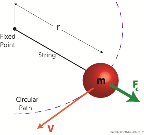
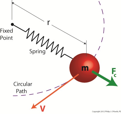
Figure 1 shows a red ball, whose mass we’ll notate m, attached to a string, the other end of which is attached to a fixed point, such as if you held it taught between your fingers. If you’re in a playful mood, you might enjoy twirling the ball above your head on its string. The distance between the center of the ball and the fixed point is labeled r, which stands for the radius of the circular path traveled by the ball as it twirls around the fixed point. The speed at which the ball travels through the air is called its straight line velocity, or tangential velocity in scientific-speak, and it is generally notated as a V. The centrifugal force, or Fc, that is exerted upon the ball as it whirls around your head is, Sir Isaac tells us, measured by the equation: Fc = mV2/r Centrifugal force in the simplest of terms is an outward-pushing force that pulls objects in motion away from the point about which they’re rotating. Let’s hold as fact that if m and r don’t change, then Newton’s equation tells us that the centrifugal force exerted upon the object in motion increases by the square of the velocity, or speed, of the ball. In other words, the faster the ball moves as you spin it around your head on the string, the harder the centrifugal force that acts upon it. As you spin the ball faster and faster, it will pull outward more and more strenuously, exerting ever greater resistance upon the string you hold between your fingers. Now suppose we replace the string in this example with a spring as shown in Figure 2. Figure 2
Why a spring? Because that’s what’s used within a centrifugal clutch. Just as with the string, the ball’s velocity increases as you increase rotation speed around the fixed point, and the centrifugal force acting upon its mass by the spinning action increases as well. The spring expands, extending further and further out from its beginning position of attachment to the fixed point, your fingers. As velocity decreases, the spring will retract, eventually returning to its original coil size. This extending and retracting action is the major mechanism at play within a centrifugal clutch. Next time we’ll explore a centrifugal clutch mechanism in more depth to observe its behavior relative to its spring under the influence of centrifugal force. ____________________________________________
|


