| If you’ve been following along with our blog discussion on the systems engineering approach to medical device design, you should by now be convinced that instructions are important. In fact, the meticulous instructions produced during the manufacturing, operating, and maintenance phases of the Development stage are also crucial to later stages, that of Production and Utilization. Let’s finish up our discussion on the Development stage by taking a look at its final aspect, Preproduction.
The Preproduction aspect is instrumental to nipping potential problems in the bud before the medical devices go into actual production. In the initial Preproduction stages, systems engineers coordinate with the manufacturing and purchasing departments within the company as well as outside suppliers. The goal is to acquire all parts and equipment necessary to build a limited number of medical devices on the assembly line. Subjects such as preference in molded plastic components, motors, gears, pumps, springs, electronic components, circuit boards, wire, and tubing are discussed and agreed upon. Vendors are assessed with regard to their ability to produce parts when they are needed and that meet design specifications, satisfy quality requirements, and have costs that fall within budgetary constraints. The assembly of Preproduction devices provides an opportunity for systems engineers to validate manufacturing and quality control instructions and assess the device design with regard to manufacturability, meaning, the extent to which devices can be manufactured with relative ease, at minimal cost, while maintaining maximum reliability. Devices manufactured during this aspect of the Development stage serve as a test. Are instructions clearly written? Do the device parts fit together as they should? Are parts strong enough to withstand the assembly process? Can the devices be assembled as quickly and easily as expected? If the answer is “no” to any of these questions, then the device design and instructions must be returned to the design engineers and technical writers. Heads come together to rehash things and work out the bugs. Next time we’ll continue with the Preproduction aspect of the Development stage to see how laboratory and field testing enables systems engineers to shake out any more bugs from the medical device design, operating instructions, and maintenance instructions. ___________________________________________ |
Posts Tagged ‘springs’
Systems Engineering In Medical Device Design – Preproduction, Part I
Monday, February 4th, 2013Mechanical Power Transmission – The Centrifugal Clutch in Operation
Sunday, April 22nd, 2012| Just the other day I unexpectedly experienced the effects of centrifugal force while driving home from the grocery store. The checker had packed my entire order into one bag, making it top heavy. Then en route someone cut me off at an intersection, and I had to make a sharp turn to avoid a crash. During this maneuver centrifugal force came into play, forcing my grocery bag out of its centered position on the front seat next to me. It lurched into the passenger’s door, fell over, and spilled its contents onto the floor. Fortunately the eggs didn’t get smashed.
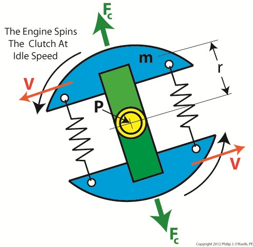
In previous articles we identified the component parts of a centrifugal clutch mechanism and learned how centrifugal force makes objects spinning in a circular path about a fixed point move outward. We can now explore what happens when we couple a centrifugal clutch mechanism to the engine of a grass trimmer. Figure 1 depicts the spinning clutch mechanism of a gas engine when it’s just been started and is operating at a slow idle speed. Figure 1
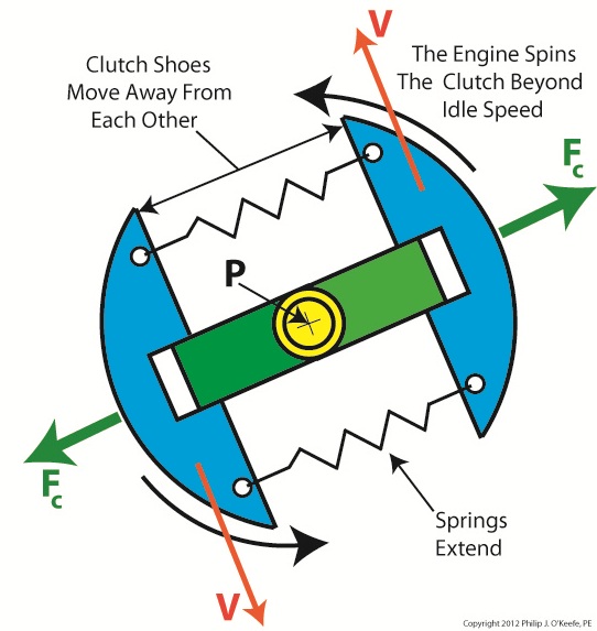
Like the red ball in my previous article on centrifugal force, the blue centrifugal clutch shoes each have a mass m. They spin around a fixed point P, situated at the center of the yellow engine shaft coupling. Point P is located a distance r from the center of each shoe. The shoes in motion have a tangential velocity V, and in accordance with Sir Isaac Newton’s Law of Centrifugal Force, the force Fc acts upon each shoe, causing them to want to pull out from the center of the mechanism, away from the fixed point. Since idle speed is rather slow, however, the centrifugal force exerted upon the shoes isn’t strong enough to overcome the tension of the two springs and the coils connecting them remain coiled, holding the shoes tightly in position on the green boss. So what happens when we press the throttle trigger on the gas engine and cause the engine to speed up? See Figure 2. Figure 2
Figure 2 shows the clutch mechanism spinning at an increased velocity. The tangential velocity V increases, and according to Newton’s law, the centrifugal force Fc acting on the clutch shoes increases as well. The force is so strong that it overcomes the tension in the springs and they extend. The clutch shoes are caused to move out and away from fixed point P, as well as from each other, traveling along the ends of the boss. When we remove our finger from the throttle trigger, the engine will slow down and return to idle speed. The centrifugal force will decrease and the springs will pull the shoes back towards fixed point P. The mechanism will return to its previous state, as shown in Figure 1. Next time we’ll insert the centrifugal clutch mechanism into the clutch housing to see how mechanical power is transmitted from the engine to the cutter head in our grass trimmer. ____________________________________________
|
Mechanical Power Transmission – The Centrifugal Clutch Mechanism
Sunday, April 15th, 2012| My journey through engineering school was marked by a cast of colorful characters from around the world. I remember one Russian professor in particular, fond of extolling the virtues of Russian engineering by the statement, “In Soviet Union steel ingots roll in one door, military tanks roll out other door.” During that period of history in his homeland, it was not uncommon for all components down to the smallest screw to be manufactured within the same factory.
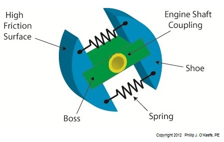
That professor taught me all about clutch mechanisms, and whether they’re present in Soviet tanks or grass trimmers they perform the same basic function. Let’s take a look at one now. Figure 1
Figure l shows my color-enhanced clutch illustration, which makes it easy to identify the different components of a centrifugal clutch. The main part of the clutch is colored green and it’s respectfully referred to as the “boss.” I assume it’s earned the title due to its role in keeping all component parts of the clutch assembly together. The blue portion shows two clutch shoes. The boss fits loosely into notches within the shoes. The curved surfaces on the shoes are composed of a high friction material, and we’ll see why later. Two springs attached to the shoes cause them to pull towards each other and keep them from falling off the ends of the boss. The yellow portion shows the engine shaft coupling. It’s permanently affixed to the center of the boss. This coupling has a hole in it that enables the clutch mechanism to be attached onto an engine shaft with a threaded nut or some other type of mechanical fastener. Now that we’re familiar with a centrifugal clutch’s parts we can see how they come into play in a real world application, that of an engine shaft. We’ll explore that next week. ____________________________________________
|
