|
Inertia. It’s the force that keeps us in bed after the alarm has rung. It seems to have a life of its own, and today we’ll see how it comes into play in keeping other stationary objects at rest. Last time we identified a specific point of contact between spur gear teeth in a gear train and introduced the opposing forces, F1 and F 2, generated there. Today we’ll see what these forces represent, identifying one of them as inertia.
So where do these forces come from? They’re forces generated by different means that converge at the same point of contact, the point at which gear teeth mesh. They follow a very specific geometric path to meet there, an imaginary straight line referred to as the line of action. F1 is always generated by a source of mechanical energy. In our locomotive example introduced earlier in this blog series that source is an electric traction motor, upon which a driving gear is mounted. When the motor is energized, a driving force F1 is generated, which causes gear teeth on the driving gear to push against gear teeth of the driven gear. Force F2 is not as straightforward to understand, because it’s not generated by a motor. Instead, it’s the resisting force that the weight of a stationary object poses against its being moved from an at-rest position, known as inertia. The heavier the object, the more inertia it presents with. Trains, of course, are extremely heavy, and to get them to move a great deal of inertia must be overcome. Inertia is also a factor in attempting to stop objects already in motion. To get a stationary locomotive to move, mechanical energy must be transmitted from the driving gear that’s attached to its traction motor, then on to the driven gear attached to its axle. At their point of contact, the driving force of the motor, F1, is met by the resisting force of inertia, F2. In order for the train to move, F1 must be greater than F2. If F1 is less than or equal to F2, then the train won’t leave the station. Next week we’ll animate our static image and watch the interplay between gear teeth, taking note of the line of action during their movement.
_______________________________________ |
Posts Tagged ‘traction motor’
Overcoming Inertia
Monday, February 3rd, 2014
Spur Gear Tooth Geometry and the Involute Curve
Sunday, January 19th, 2014|
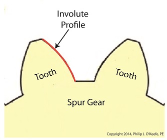
Last time we learned how spur gears mesh together to form a gear train and we examined a train consisting of just two gears, one being the driving gear, the other the driven gear. Today we’ll take a look at the geometry behind the smooth functioning of modern spur gear teeth when we identify their peculiar shape to be that of an involute curve. The curved profile of spur gear teeth conforms to a type of mathematical curve found in geometry known as an involute. The involute profile of a spur gear tooth is shown in red below. The mathematical notion of the involute was first presented in 1673 by Dutch mathematician Christiaan Huygens, in his book, Horologium Oscillatorium. Huygens’ book presents his studies on clock pendulums and the applied mathematics he used in an effort to predict their often erratic motion on ships at sea. His book ultimately dealt with far more than this, resulting in a treatise on the mathematical properties of the involutes of curves. To see how an involute curve is formed, we’ll conduct a simple experiment. One end of string is attached with a tack to a circular object, like the yellow rod shown in the following illustration. The other end of string has a red ball attached to it.
 Forming An Involute Curve If we grab the ball and pull the string taught while wrapping the string around the rod, the ball’s path will form an involute curve due to the incremental shortening of the string that occurs as it wraps around the rod. Next time we’ll see how the involute profile of gear teeth contributes to efficient mechanical energy transmission in gear trains. _______________________________________ |

Gear Trains
Monday, January 13th, 2014|
Last time we covered the basic terminology of spur gears. Today we’ll see how they interact with one another to form a gear train, such as the one depicted below.
 Meshing Spur Gears Form A Gear Train A gear train is formed when the teeth of two or more gears mesh and work together for the purpose of powering a mechanical device. A gear train can consist of as little as two gears, but trains can be so large as to contain dozens of gears, depending on the complexity of the device they are powering. But no matter how many gears are employed, there are certain key features that are shared by every gear train assembly. First, one gear within the train must be attached to a shaft rotated by a source of mechanical energy, such as an engine or electric motor. This gear is called the driving gear. The second requirement of a gear train is that at least one gear other than the driving gear is mounted to the shaft of a rotating machine part. This gear is called the driven gear.
 Locomotive Gear Train Consisting Of Two Gears The illustration above shows an exploded view of a locomotive gear train assembly consisting of two gears. The driving gear is mounted to the shaft of an electric traction motor. The driven gear is mounted to the locomotive’s axle. When a motor is attached to the axle, the two gears mesh together. The traction motor converts electrical energy into mechanical energy, which is supplied to the driving gear via the spinning motor’s shaft. The teeth of the driving gear then transmit the motor’s mechanical energy to the teeth of the driven gear, which then turn the locomotive’s wheels. It’s just one of countless operations that can be performed with gear train assemblies. Next time we’ll examine the geometry behind modern spur gear tooth design. _______________________________________ |
Regenerative Brakes
Sunday, June 13th, 2010|
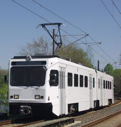
Have you ever been stranded on a subway car? The lights flickered wildly, then the odd humming sounds all came to an abrupt stop, and you sat there exchanging uncomfortable glances with your fellow passengers? “Hey, get this thing going! I’ve got an appointment to make!” someone shouts at the driver, sequestered in his cab. The trouble is, he, like the rest of the passengers, is equally helpless in this situation. You see, streetcars, subway cars, and light rail cars are all forms of electric railway cars, and when their source of electricity goes out, so do they. They’re similar to the diesel-electric locomotive we looked at last week because they use electric traction motors for propulsion, meaning to move forward. But their difference lies in the fact that electric rail cars don’t carry their own source of power and are entirely reliant on an external source, an electrical substation. See Figure 1 below.
Figure 1 – Electric Railway Car Propulsion System This substation performs the task of taking the power provided by an electric utility power plant and converting it into a form of power that the electric rail car can use to operate its traction motors. The two are connected via a trolley wire and the two rails that the car runs on. The railway car has a spring-loaded arm called a pantograph on its roof that touches the trolley wire, allowing electrical current to flow into a speed control system housed under the car. This speed control system performs the task of varying the flow of electrical current to the traction motors, enabling the car to move, before it eventually exits the motor through its wheels, then back to the substation where it originated, thus completing an electrical circuit. Many newer electric railway cars couple a regenerative braking system with a mechanical one. Their operation is similar in nature to a dynamic braking system where the traction motors are turned into generators. The difference is that with regenerative braking systems the current from the traction motors is sent to the trolley wire through the pantograph as shown in Figure 2 below.
Figure 2 – An Electric Railway Car Using Regenerative Brakes This diagram shows the railcar generating electricity, but it may not be so obvious how its motion is made to slow down, after all, we see no resistor grids like we did in last week’s illustration of a dynamic braking system. So how does it stop? The trick here is that there are other cars running on the rail line at the same time which are using electrical current to move forward. So what does this have to do with stopping it you ask? Let’s take a look at Figure 3 for clarification. Figure 3 – How Regenerative Brakes Help Save Power In this illustration we see that as Car A goes downhill and the operator applies the brakes, the regenerative brake will be caused to start pumping electrical current into the trolley wire. Now, if Car B is on the same rail line going up the other side of the hill, it will need power to climb that hill, and it will need to draw that power from the trolley wire by way of its pantograph. But instead of drawing all its electrical current from the substation, Car B will first draw off the current produced by nearby Car A, and only then will it draw the remainder of its power requirements from the substation. During this braking process the kinetic energy in Car A is converted into electrical energy by its traction motors. Then Car B uses its own traction motors to convert the electrical energy drawn from Car A into mechanical energy, enabling it to climb the hill. Car B has effectively robbed Car A of its energy, so Car A slows down. As we discovered last week during our discussion of dynamic brakes, regenerative brakes become ineffective below a certain minimum speed. This is the reason that electric rail cars need mechanical brakes to complete the job of stopping. We see that the regenerative braking process is actually quite green. It allows for electrical energy that would normally be wasted as heat energy escaping into the atmosphere to be converted into useful energy, taking a significant chunk out of the demand for new energy off of substations. It also helps the electric railway to save money when it comes time to paying the electric bills. You may have noticed a copyright symbol and my name included in this week’s illustrations. That’s because it has recently come to my attention that many of my readers are unaware that I am the CAD (Computer Aided Design) artist who creates the illustrations featured in most of my blogs. CAD is a useful tool in explaining difficult technical subject matter, which is precisely why I use it so often. Next week we’ll explore in more depth the benefits of using this tool.
_____________________________________________
|


Diesel Locomotive Brakes
Sunday, June 6th, 2010|
In the past few weeks we’ve taken a look at both mechanical and dynamic brakes. Now it’s time to bring the two together for unparalleled stopping performance. Have you ever wandered along a railroad track, hopping from tie to tie, daring a train to come roaring along and wondering if you could jump to safety in time? Many have, and many have lost the bet. That’s because a train, once set into motion, is one of the hardest things on Earth to bring to a stop. In this discussion, let’s focus on the locomotive. A large, six-axle variety is shown in Figure 1.
Figure 1 – A Six-Axle Diesel-Electric Locomotive These massive iron horses are known in the industry as diesel-electric locomotives, and here’s why. As Figure 2 shows, diesel-electric locomotives are powered by huge diesel engines. Their engine spins an electrical generator which effectively converts mechanical energy into electrical energy. That electrical energy is then sent from the generator through wires to electric traction motors which are in turn connected to the locomotive’s wheels by a series of gears. In the case of a six-axle locomotive, there are six traction motors all working together to make the locomotive move. So how do you get this beast to stop? Figure 2 – The Propulsion System In A Six-Axle Diesel-Electric Locomotive You probably noticed in Figure 2 that there are resistor grids and cooling fans. As long as you’re powering a locomotive’s traction motors to move a train, these grids and fans won’t come into play. It’s when you want to stop the train that they become important. That’s when the locomotive’s controls will act to disconnect the traction motor wires running from the electrical generator and reconnect them to the resistor grids as shown in Figure 3 below.
Figure 3 – The Dynamic Braking System In A Six-Axle Diesel Electric Locomotive The traction motors now become generators in a dynamic braking system. These motors take on the properties of a generator, converting the moving train’s mechanical, or kinetic, energy into electrical. The electrical energy is then moved by wires to the resistor grids where it is converted to heat energy. This heat energy is removed by powerful cooling fans and released into the atmosphere. In the process the train is robbed of its kinetic energy, causing it to slow down. Now you may be thinking that dynamic brakes do all the work, and this is pretty much true, up to a point. Although dynamic brakes may be extremely effective in slowing a fast-moving train, they become increasingly ineffective as the train’s speed decreases. That’s because as speed decreases, the traction motors spin more slowly, and they convert less kinetic energy into electrical energy. In fact, below speeds of about 10 miles per hour dynamic brakes are essentially useless. It is at this point that the mechanical braking system comes into play to bring the train to a complete stop. Let’s see how this switch from dynamic to mechanical dominance takes place. A basic mechanical braking system for locomotive wheels is shown in Figure 4. This system, also known as a pneumatic braking system, is powered by compressed air that is produced by the locomotive’s air pump. A similar system is used in the train’s railcars, employing hoses to move the compressed air from the locomotive to each car.
Figure 4 – Locomotive Pneumatic Braking System In the locomotive pneumatic braking system, pressurized air enters an air cylinder. Once inside, the air bears against a spring-loaded piston, as shown in Figure 4(a). The piston moves, causing brake rods to pivot and clamp the brake shoes to the locomotive’s wheel with great force, slowing the locomotive. When you want to get the locomotive moving again, you vent the air out of the cylinder as shown in Figure 4(b). This takes the pressure off the piston, releasing the force from the brake shoes. The spring in the cylinder is now free to move the shoes away from the wheel so they can turn freely. We have now returned to the situation present in Figure 2, and the locomotive starts moving again. Next week we’ll talk about regenerative braking, a variation on the dynamic braking concept used in railway vehicles like electric locomotives and subway trains. _____________________________________________
|


