|
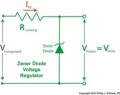
Last time we learned how the transistor opens a path for electric current to flow from the collector to the emitter in our example circuit. It does so by making use of an unregulated power supply. Now let’s see how the Zener diode fits into the mix.

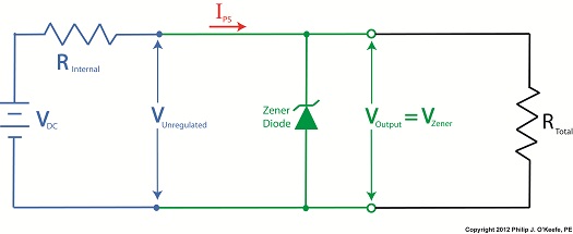
Figure 1
It just so happens that bipolar transistors, like the one in our example circuit in Figure 1, are designed so that voltage at its emitter is dependent upon the voltage applied at its base. This makes them ideal for use in voltage regulator circuits where this kind of predictability is required.
For example, in our transistor series voltage regulator, the Zener diode is connected to the transistor’s base, B. When the branch current flows from RLimiting down through the diode, a Zener voltage, VZener, is established. Since the diode is connected to the transistor, VZener voltage is also applied to the transistor’s base. Thus the transistor’s emitter voltage will be regulated according to the Zener voltage.
Bipolar transistors are designed by manufacturers to typically operate with a standardized voltage difference of 0.6 volts between the base and emitter. This is represented in Figure 1 as VBE, where BE stands for base-emitter. VBE is standardized at a known quantity of 0.6 volts to simplify things within the industry and aid engineers in their calculations to design transistor circuits, as we’ll now see.
With the Zener diode connected to the transistor base in our example circuit, the voltage difference is denoted as:
VBE = VZener – VE
where VE is the emitter voltage. Rearranging terms to solve for VE, we get:
VE = VZener – VBE
Inserting VBE, which we know is standardized at 0.6 volts:
VE = VZener – 0.6 volts
Since the emitter is physically connected to the output terminal of the transistor series voltage regulator, the emitter voltage is going to be equal to the output voltage, VOut.
We learned earlier in this series of articles that VZener is a reliable source of consistent voltage. Because it is present in our transistor series voltage regulator, our example circuit will produce a nice, constant regulated output voltage of VZener – 0.6 volts, a voltage that is useful for many of today’s applications. However the transistor series voltage regulator provides us with a major advantage over the Zener diode voltage regulator circuit.
The advantage of a transistor series voltage regulator lies in the fact that RLimiting is on a separate branch all to its own within the regulator circuit, and because of this it no longer acts as a roadblock to limit the main path of current flow, as happens within the Zener diode voltage regulator circuit discussed previously. Refer to the red path shown in Figure 1. With RLimiting in this position the transistor series voltage regulator is able to feed more current to the external supply circuit than is possible through the Zener diode voltage regulator alone. This means it can be used in more power hungry applications like energizing today’s TVs and modern kitchen appliances.
That wraps up our discussion on transistors. Next time we’ll begin a new topic, how medical devices can be designed using systems engineering, a systematic approach that ensures that designed devices satisfy both user and regulatory requirements.
____________________________________________
|


 Engineering Expert Witness Blog


