Posts Tagged ‘wires’

Converting Kinetic Energy to Electrical Energy

Tuesday, November 3rd, 2015

     When acting as an engineering expert I’m often called upon to investigate incidents where energy converts from one form to another, a phenomenon that James Prescott Joule observed when he built his apparatus and performed his experiments with electricity.   Today we’ll apply Joule’s findings to our own experiment with a coffee mug when we convert its kinetic energy into electrical energy and see how the units used to express that energy also change. 

     We had previously calculated the kinetic energy contained within our falling coffee mug to be 4.9 kg • meter2/second2, also known as 4.9 Joules of energy, by using de Coriolis’ Kinetic Energy Formula.   Now most of us don’t speak in terms of Joules of energy, but that’s easily addressed.   As we learned in a previous blog on The Law of Conservation of Energy, all forms of energy are equivalent and energy can be converted from one form to another, and when it does, the unit of energy used to express it also changes.

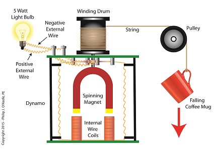
     Let’s say we want to put our mug’s 4.9 Joules of kinetic energy to good use and power an electric light bulb.   First we must first find a way of converting the mug’s kinetic energy into electrical energy.   To do so, we’ll combine Joule’s apparatus with his dynamo, and connect the mug to this hybrid device with a string.

Converting Kinetic Energy to Electrical Energy

                     Converting Kinetic Energy to Electrical Energy

     As the mug falls its weight tugs on the string, causing the winding drum to rotate.   When the drum rotates, the dynamo’s magnet spins, creating electrical energy.   That’s right, all that’s required to produce electricity is a spinning magnet and coils of wire, as explained in my previous blog, Coal Power Plant Fundamentals – The Generator.

     Now we’ll connect a 5 Watt bulb to the dynamo’s external wires.   The Watt is a unit of electrical energy named in honor of James Watt, a pioneer in the development of steam engines in the late 18th Century.

     Now it just so happens that 1 Watt of electricity is equal to 1 Joule of energy per a specified period of time, say a second.   This relationship is expressed as Watt • second.   Stated another way, 4.9 Joules converts to 4.9 Watt • seconds of electrical energy.   Let’s see how long we can keep that 5 Watt bulb lit with this amount of energy.    Mathematically this is expressed as,

Lighting Time = (4.9 Watt • seconds) ÷ (5 Watts) = 0.98 seconds

     This means that if the mug’s kinetic energy was totally converted into electrical energy, it would provide enough power to light a 5 Watt bulb for almost 1 second.

     Next time we’ll see what happens to the 4.9 Joules of kinetic energy in our coffee mug when it hits the floor and becomes yet another form of energy.

Copyright 2015 – Philip J. O’Keefe, PE

Engineering Expert Witness Blog

____________________________________

Industrial Control Basics – Disconnect Switches

Sunday, March 25th, 2012
     Last week our kitchen ceiling fan and light combo decided to stop working.  We don’t like eating in the dark, so I was compelled to do some immediate troubleshooting.  As an engineer with training in the workings of electricity I have a great respect for it.  I’m well aware of potential hazards, and I took a necessary precaution before taking things apart and disconnecting wires.  I made the long haul down the stairs to the basement, opened the circuit breaker in the electrical panel, and disabled the flow of electricity to the kitchen.  My fears of potential electrocution having been eliminated, my only remaining fear was of tumbling off the ladder while servicing the fan.

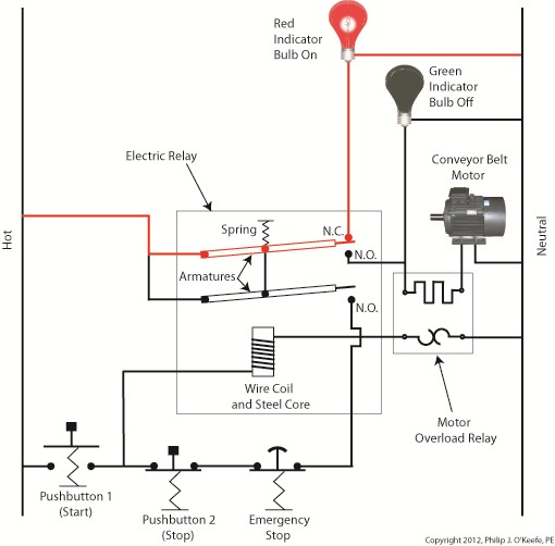
     Just as I took the precaution to disconnect the power supply before performing electrical maintenance in my home, workers in industrial settings must do the same, and a chief player in those scenarios is the motor overload relay discussed last week.  It automatically shuts down electric motors when they become overheated.  Let’s revisit that example now.

Industrial Control System

Figure 1


     Our diagram in Figure 1 shows electric current flowing through the circuit by way of the red path.  Even if this line were shut down, current would continue to flow along the path, because there is no means to disconnect the entire control system from the hot and neutral lines supplying power to it, that is, it is missing disconnect switches.  Electric current will continue to pose a threat to workers were they to attempt a repair to the system.  Now let’s see how we can eliminate potential hazards on the line.

Disconnect Switches

Figure 2


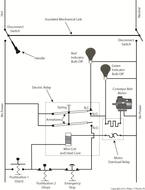
     In Figure 2 there is an obvious absence of the color red, indicating the lack of current within the system.  We accomplished this with the addition of disconnect switches capable of isolating the motor control circuitry, thereby cutting off the hot and neutral lines of the electrical power supply and along with it the unencumbered flow of electricity.

    These switches are basically the same as those seen in earlier diagrams in our series on industrial controls, the difference here is that the two switches are tied together by an insulated mechanical link.  This link causes them to open and close at the same time.  The switches are opened and closed manually via a handle.  When the disconnect switches are both open electricity can’t flow and nothing can operate.  Under these conditions there is no risk of a worker coming along and accidentally starting the conveyor motor.

     To add yet another level of safety, disconnect switches are often tagged and locked once de-energized.  This prevents workers from mistakenly closing them and starting the conveyor while maintenance is being performed.  Brightly colored tags alert everyone that maintenance is taking place and the switches must not be closed.  The lock that performs this safety function is actually a padlock.  It’s inserted through a hole in the switch handle, making it impossible for anyone to flip the switch.  Tags and locks are usually placed on switches by maintenance personnel before repairs begin and are removed when work is completed.

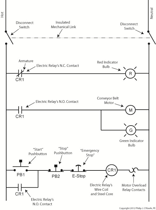
     Now let’s see how our example control system looks in ladder diagram format.

Control System Ladder Diagram

Figure 3


     Figure 3 shows a ladder diagram that includes disconnect switches, an emergency stop button, and the motor overload relay contacts.  The insulated mechanical link between the two switches is represented by a dashed line.  Oddly enough, engineering convention has it that the motor overload relay heater is typically not shown in a ladder diagram, therefore it is not represented here.

     This wraps up our series on industrial control.  Next time we’ll begin a discussion on mechanical clutches and how they’re used to transmit power from gasoline engines to tools like chainsaws and grass trimmers.

____________________________________________


Industrial Control Basics – Ladder Diagrams

Sunday, December 18th, 2011
     The other day I pressed the button to activate my electric garage door opener and nothing happened.  I pushed again and again, still nothing.  Finally, I convinced myself to get out of the car and take a closer look.  A wooden board I had propped up against the side of the garage wall had come loose, wedging itself in front of the electric eye, you know, the one that acts as a safety.  The board was an obstruction to the clear vision of the eye.  It couldn’t see the light emitter on the other side of the door opening and wouldn’t permit the door opener to function.

     The basic manual control system we looked at last week operates similarly to the eye on a garage door opener.  If you can’t “close the loop,” you won’t get the power.  Last week’s example was as basic as things get.  Now let’s look at something a bit more complex.

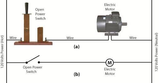
     Words aren’t always the best vehicle to facilitate understanding, which is why I often use visual aids in my work.  In the field of industrial control systems diagrams are often used to illustrate things.  Whether it’s by putting pencil to paper or the flow diagram of software logic, illustrations make things easier to interpret.  Diagrams such as the one in Figure l are often referred to as “ladder diagrams,” and in a minute we’ll see why.

Figure 1

     Figure 1(a) shows a basic manual control system.  It consists of wires that connect a power switch and electric motor to a 120 volt alternating current power source.  One wire is “hot,” the other “neutral.”  The hot side is ungrounded, meaning that it isn’t electrically connected to the Earth.  The neutral side is grounded, that’s right, it’s driven into the ground and its energy is dissipated right into the earth, then returned back to the power grid.  In Figure 1(a) we see that the power switch is open and an air gap exists.  When gaps exist, we don’t have a closed electrical loop, and electricity will not flow.    

     Figure 1(b), our ladder diagram, aka line diagram, shows an easier, more simplified representation of the manual control shown in Figure 1(a).  It’s easier to decipher because there’s less going on visually for the brain to interpret.  Everything has been reduced to simple lines and symbols.  For example, the electric motor is represented by a symbol consisting of a circle with an “M” in it.

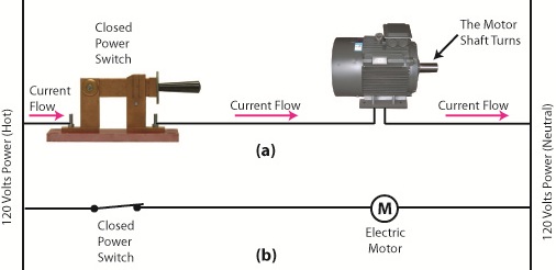
     Now, let’s turn our attention to Figure 2 below to see what happens when the power switch is closed.

Figure 2

     The power switch in Figure 2(a) is closed, allowing electric current to flow between hot and neutral wires, then power switch, and finally to the motor.  The current flow makes the motor come to life and the motor shaft begins to turn.  The line diagram for this circuit is shown in Figure 2(b).

     You might have noticed that the line diagrams show in Figures 1(b) and 2(b) have a rather peculiar shape.  The vertically running lines at either side depict the hot and neutral legs of the system.  If you stretch your imagination a bit, they look like the legs of a ladder.  Between them run the wires, power switch, and motor, and this horizontal running line represents the rung of the ladder.  More complicated line diagrams can have hundreds, or even thousands of rungs, making up one humongous ladder, hence they are commonly referred to as ladder diagrams.

     Next week we’ll take a look at two key elements in automatic control systems, the push button and electric relay, elements which allow us to do away with the need for human intervention.

____________________________________________