| What do wall warts, aka AC wall adapters, and microwave ovens have in common? Well, in previous blogs discussing microwaves, we saw how a microwave oven’s high voltage circuitry uses a transformer, diode, and capacitor to effectively convert AC voltage into DC voltage. Wall warts do much the same thing and in very much the same way.
If you will recall from our discussion of microwave ovens in the past few weeks, the transformer in a high voltage circuit transforms 120 volts into a much higher voltage, say 4000 volts, in order to make things work. The diode and capacitor within both the microwave and the wall wart are key to facilitating this magical act, but in the wall wart it happens at a much lower voltage, about 12 volts. Last week we began exploring the inner workings of the wall wart. We discovered how its transformer converts the 120 volts emanating from your average wall outlet to the 12 volts required by most electronic devices. These voltages are shown at Points A and B in Figure 1 below. The fact that the voltage being put out results in waves of energy which alternate between a positive maximum value, zero, and a negative maximum value, makes it an unacceptable power source for most electronic devices. They require voltage that doesn’t alternate, and this is where the wall wart’s diode bridge and capacitor come into play.
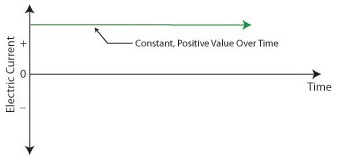
Figure 1 – The Workings of the Wall Wart Transformer The wall wart’s diode bridge consists of four electronic components, namely the diodes, which are connected together. This diode bridge goes a bit further than the single diode present in a microwave oven, because it doesn’t merely eliminate negative aspects of alternating voltage. It actually transforms negative voltage into positive voltage. The result is a series of 12 volt peaks as shown at Point C of Figure 1. In fact, we end up with twice as many voltage peaks, and this is important, as you’ll see below. We still have the problem of zero voltage gaps to address. You see, over time the voltage at Point C of Figure 1 keeps changing between 0 volts and positive 12 volts. This can lead to problems, because many electronic devices require a consistent voltage of greater than zero to operate properly. For example, a light emitting diode (LED) might develop an annoying flicker, or you might end up hearing an irritating hum while listening to the radio. These annoyances are virtually eliminated by feeding voltage from the diode bridge into the capacitor, which gets rid of the zero voltage gaps between the voltage peaks. Like a microwave’s capacitor, the one within a wall wart charges up with electrical energy as the voltage from the diode bridge nears the top of a peak. Then, as voltage begins its dive back to a zero value, the capacitor discharges its electrical energy to fill in the gaps between peaks. The result is the rippled voltage pattern at Point D of Figure 1. With the gaps filled in, the voltage is at, or close enough to, the 12 volts required to keep an electronic device operating properly when it is connected to the wall wart’s low voltage power cord. Well, that’s it for our look at the wall warts that power our myriad of electronic devices. Next time we’ll switch to a totally topic and look at some of the basics of food manufacturing equipment design. ____________________________________________ |
Posts Tagged ‘AC adapter’
Further Inside the Wall Wart
Sunday, September 11th, 2011
Inside The Wall Wart
Monday, September 5th, 2011|
What would a cop show be without a crime scene, or better yet the obligatory dissection at the morgue? Forensic doctors performing autopsies have become commonplace, the clues they provide indispensable. Forensic engineers such as myself do much of the same thing, working our way backwards through time by dissecting industrial equipment and consumer products left in the wake of fires, injuries, and deaths. Let’s do some forensic dissecting now to see what’s in a wall wart and how it works. The inside of a basic wall wart is shown in Figure 1.
Figure 1 – Inside The Wall Wart You’ll note that a wall wart has four main components: a transformer, diode bridge, capacitor, and a printed circuit board (PCB). The PCB is constructed of plastic resin upon which is mounted copper strips. This makes a rigid platform base upon which electronic components are attached, namely the transformer, diode bridge, and capacitor. These components are soldered to the PCB, tying them together both mechanically and electrically. Now let’s see how the components of the wall wart work together to change the 120 volts coming from your standard wall outlet into the 12 volts needed to power a typical electronic device. We’ll use an instrument known as an oscilloscope to help us visualize what’s going on. See Figure 2.
Figure 2 – The Workings of the Wall Wart Transformer What is depicted in the graph above is the oscilloscope’s ability to receive an electronic signal, measure it, graph it, and then display it on a screen. This enables us to see how the signal changes over time. At Point A, which represents the wall wart plugged into a wall outlet, the voltage alternates between positive 120 volts and negative 120 volts upon entering the wall wart, which will now act as a transformer. The wall wart transformer then does as its name suggests, it transforms the 120 volts coming from the outlet into the 12 volts shown at Point B. You will note that this lower voltage also alternates between positive and negative values, just as the original 120 volts emanating from the wall outlet did. In one of my earlier blogs I explained that transformers only work when the electricity passing through them alternates over time. (Click here for a refresher: Transformers ) High voltage alternating electricity in one transformer coil creates magnetic fields that induce alternating electricity at a different voltage in a second transformer coil. So when you put alternating voltage into the transformer, you get alternating voltage out. But that’s not the end of the story. Many electronic devices operate on voltage that doesn’t alternate. What then? Will our handy wall wart still be able to bridge the electrical gap to fill our needs? Next time we’ll see how the diode bridge and capacitor come into play to deal with the alternating voltage from the transformer in a manner eerily similar to a microwave oven’s high voltage circuit. ____________________________________________ |


