|
Last time we saw how a gear reduction does as its name implies, reduces the speed of the driven gear with respect to the driving gear within a gear train. Today we’ll see how to work the problem in reverse, so to speak, by determining how many teeth a driven gear must have within a given gear train to operate at a particular desired revolutions per minute (RPM). For our example we’ll use a gear train whose driving gear has 18 teeth. It’s mounted on an alternating current (AC) motor turning at 3600 (RPM). The equipment it’s attached to requires a speed of 1800 RPM to operate correctly. What number of teeth must the driven gear have in order to pull this off? If you’ve identified this to be a word problem, you’re correct.
Let’s first review the gear ratio formulas introduced in my previous two articles: R = nDriving ÷ nDriven (1) R = NDriven ÷ NDriving (2) Our word problem provides us with enough information so that we’re able to use Formula (1) to calculate the gear ratio required: R = nDriving ÷ nDriven = 3600 RPM ÷ 1800 RPM = 2 This equation tells us that to reduce the speed of the 3600 RPM motor to the required 1800 RPM, we need a gear train with a gear ratio of 2:1. Stated another way, for every two revolutions of the driving gear, we must have one revolution of the driven gear. Now that we know the required gear ratio, R, we can use Formula (2) to determine how many teeth the driven gear must have to turn at the required 1800 RPM: R = 2 = NDriven ÷ NDriving 2 = NDriven ÷ 18 Teeth NDriven = 2 × 18 Teeth = 36 Teeth The driven gear requires 36 teeth to allow the gear train to operate equipment properly, that is to say, enable the gear train it’s attached to provide a speed reduction of 1800 RPM, down from the 3600 RPM that is being put out from the driving gear. But gear ratio isn’t just about changing speeds of the driven gear relative to the driving gear. Next time we’ll see how it works together with the concept of torque, thus enabling small motors to do big jobs.
_______________________________________ |
Posts Tagged ‘alternating current’
Gear Reduction Worked Backwards
Sunday, March 9th, 2014
Transistors – Voltage Regulation
Sunday, July 22nd, 2012| Electrical voltage flow and water flow have a lot in common. They’re both affected by fluctuations in supply, fluctuations which can adversely impact both performance and equipment integrity. Take for example a sprinkler that fails to cover a designated section of lawn due to heavy neighborhood demand. Everybody wants to water on the weekend when it’s been 90 degrees all week, and low water pressure is the result. There are times when it’s hard to get a glass of water. By contrast in the winter months, when water demands tend to be lower, water supplies are plentiful. This scenario of varying water pressure is analogous to what sometimes occurs within electric circuits.
In my previous blog article on wall warts, I described the operation of a simple power supply consisting of a transformer, diode bridge, and capacitor. Together, these components converted 120 volts alternating current (VAC) to 12 volts direct current (VDC). The wall wart power supply is fine for many applications, however it is unregulated, meaning if there are any sudden surges in power, such as spikes or dips caused by lightning strikes or other disturbances on the electric utility system, there could be problems.
Take for example a power supply that is used in conjunction with sensitive digital logic chips, like the one used in my x-ray film processor design shown in my last blog article. These chips are designed to run optimally on a constant voltage, like 5 VDC, and when that doesn’t happen input signals can fail to register with the computer program and cause a variety of problems, such as output signals turning on and off at will. In the film processor the drive motor may start at the wrong time or get stuck in an on modality. If power surges are high enough, microprocessor chips can get damaged, compromising the entire working unit. The output voltage of an unregulated power supply can also vary in response to power demand, just as when sprinklers don’t have sufficient water flow to cover a section of lawn. Demand for power can change within a circuit when electrical components like relays, lights, and buzzers are turned on and off by digital logic chips. Next time we’ll take a look at a basic concept of electrical engineering known as “Ohm’s Law” and how it governs the variable output voltage response of unregulated power supplies.
____________________________________________ |
Transistors – Digital Control Interface, Part IV
Monday, July 9th, 2012| The Olympic Torch relay, soon to culminate in London, is the grand daddy of all relays, starting in one country, traversing many others, then ending its journey at the site of the Olympic Games. It passes through many athletes’ hands while on its journey, its final purpose being to light the Olympic Flame. Less glamorous, though still useful, is the relay race that often takes place within digital controls.
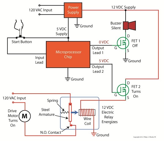
Last time we looked at my design solution for the control of a microprocessor controlled medical x-ray film developing machine, where a field effect transistor (FET) acted as a digital control interface between a 5 volt direct current (VDC) microprocessor and a 12 VDC buzzer. Well, controlling the buzzer wasn’t the only function of the microprocessor. It also had to control a 120 volt alternating current (VAC) drive motor, the purpose of which was to move x-ray film through a series of processes within the machine. Yet another requirement was that the machine’s drive motor run 40 minutes upon activation by a start button, then shut off. One of the challenges presented by this specification was that an FET standing alone is only suited to control direct current devices like the buzzer, but not alternating current devices like electric motors. Direct current flows in one direction only when traveling through wire, and since an FET can only pass current in one direction it is the perfect match for those applications. Now, as the name would imply, alternating current flow alternates, that is, it reverses direction and varies in intensity many times each second. This is a scenario that FETs are not equipped to handle because they can’t deal with reverse flow. This meant that, for the purpose of my developing machine, I could not use an FET to directly control the 120 VAC motor. Now let’s take a look at Figure 1 to get a basic look at how I solved the problem. |

Transistors – Digital Control Interface, Part II
Sunday, June 24th, 2012| Not too long ago I was retained as an engineering expert to testify on behalf of a plaintiff who owned a sports bar. The place was filled with flat screen televisions that were plugged into 120 volt alternating current (VAC) wall outlets. To make a long story short, the electric utility wires that fed power to the bar were hit by a passing vehicle, causing the voltage in the outlets to increase well beyond what the electronics in the televisions could handle. The delicate electronics were not suited to be connected with the high voltage that suddenly surged through them as a result of the hit, and they overloaded and failed.
Similarly, lower voltage microprocessor and digital logic chips are also not suited to directly connect with higher voltage devices like motors, electrical relays, and light bulbs. An interface between the two is needed to keep the delicate electronic circuits in the chips from overloading and failing like the ill fated televisions in my client’s sports bar. Let’s look now at how a field effect transistor (FET) acts as the interface between low and high voltages when put into operation within an industrial product. I was once asked to design an industrial product, a machine which developed medical x-ray films, utilizing a microprocessor chip to automate its operation. The design requirements stated that the product be powered by a 120 VAC, such as that available through the nearest wall outlet. In terms of functionality, upon startup the microprocessor chip was to be programmed to first perform a 40-minute warmup of the machine, then activate a 12 volt direct current (VDC) buzzer for two seconds, signaling that it was ready for use. This sequence was to be initiated by a human operator depressing an activation button. The problem presented by this scenario was that the microprocessor chip manufacturer designed it to operate on a mere 5 VDC. In additional, it was equipped with a digital output lead that was limited in functionality to either “on” or “off” and capable of only supplying either extreme of 0 VDC or 5 VDC, not the 12 VDC required by the buzzer. Figure 1 illustrates my solution to this voltage problem, although the diagram shown presents a highly simplified version of the end solution.
Figure 1The illustration shows the initial power supplied at the upper left to be 120 VAC. This then is converted down to 5 VDC and 12 VDC respectively by a power supply circuit. The 5 VDC powers the microprocessor chip and the 12 VDC powers the buzzer. The conversion from high 120 VAC voltage to low 5 and 12 VDC voltage is accomplished through the use of a transformer, a diode bridge, and special transistors that regulate voltage. Since this article is about FETs, we’ll discuss transistor power supplies in more depth in a future article. To make things a little easier to follow, the diagram in Figure 1 shows the microprocessor chip with only one input lead and one output lead. In actuality a microprocessor chip can have dozens of input and output leads, as was the case in my solution. The input leads collect information from sensors, switches, and other electrical components for processing and decision making by the computer program contained within the chip. Output leads then send out commands in the form of digital signals that are either 0 VDC or 5 VDC. In other words, off or on. The net result is that these signals are turned off or on by the program’s decision making process. Figure 1 shows the input lead is connected to a pushbutton activated by a human. The output lead is connected to the gate (G) of the FET. The FET is shown in symbolic form in green. The FET drain (D) lead is connected to the buzzer and its source (S) lead terminates in connection to electrical ground to complete the electrical circuit. Remember, electric current naturally likes to flow from the supply source to electrical ground within circuits, and our scenario is no exception. Next time we’ll see what happens when someone presses the button to put everything into action.
____________________________________________ |

Industrial Control Basics – Manual Control
Monday, December 12th, 2011| You’ve probably heard the saying, “asleep at the switch.” It’s usually associated with some sort of disaster, found later to have been caused by human error. Someone wasn’t paying attention, and something very bad happened. The meltdown of the Soviet nuclear power plant Chernobyl in 1986 comes to mind. You may be surprised to learn that the saying has its origins in the world of industrial controls, or more specifically, manual controls, as we’ll see in this article.
Last week when we opened our discussion on manual controls, we talked about how they work just as their name implies, that is, someone must manually press a button or throw a switch in order to initiate a factory operation. In other words, a manual control requires human intervention to initiate an action, such as pushing the start button. The machine will then continue to run until a person hits the stop button. Let’s go now on a virtual field trip into a telephone factory to see how a basic manual control system works. It has a conveyor belt operated by an electric motor, and this motor is connected by wires and a power switch to a 120 volt power source of alternating current. Figure 1 illustrates what we mean. It shows that when the power switch is in the open position, a physical air gap exists within the electrical circuit. This prevents electricity from flowing through the wire because electricity can’t jump over gaps.
Figure 1 – Open Power Switch Enter a human into the scenario, someone who grabs the power switch handle and manually closes it, eliminating the air gap. See Figure 2.
Figure 2 – Closed Power Switch When the power switch is closed, a metal conductor bridges the gap, causing electricity to flow through the metal conductor to the electric motor in the circuit. This brings life to the conveyor belt. As long as the power switch remains closed, the conveyor belt will continue to operate. That’s it, that’s a basic manual control system. It’s simple to operate, but it does have one major flaw. It requires constant monitoring by a human. Aside from opening and closing a power switch, humans are required to monitor operations, in case something goes wrong. The operator watching over an industrial machine performs the same function as the pilot on a plane, that is, to start-stop operations, and to intervene in case of an emergency. Computers fly modern jets. Pilots serve as trouble shooters when the unanticipated disaster situation occurs, because computers can’t yet creatively problem solve. Next time we’ll introduce the element of an automatic control system, which will virtually eliminate the need for human intervention and with it human error. ____________________________________________ |


Inside The Wall Wart
Monday, September 5th, 2011|
What would a cop show be without a crime scene, or better yet the obligatory dissection at the morgue? Forensic doctors performing autopsies have become commonplace, the clues they provide indispensable. Forensic engineers such as myself do much of the same thing, working our way backwards through time by dissecting industrial equipment and consumer products left in the wake of fires, injuries, and deaths. Let’s do some forensic dissecting now to see what’s in a wall wart and how it works. The inside of a basic wall wart is shown in Figure 1.
Figure 1 – Inside The Wall Wart You’ll note that a wall wart has four main components: a transformer, diode bridge, capacitor, and a printed circuit board (PCB). The PCB is constructed of plastic resin upon which is mounted copper strips. This makes a rigid platform base upon which electronic components are attached, namely the transformer, diode bridge, and capacitor. These components are soldered to the PCB, tying them together both mechanically and electrically. Now let’s see how the components of the wall wart work together to change the 120 volts coming from your standard wall outlet into the 12 volts needed to power a typical electronic device. We’ll use an instrument known as an oscilloscope to help us visualize what’s going on. See Figure 2.
Figure 2 – The Workings of the Wall Wart Transformer What is depicted in the graph above is the oscilloscope’s ability to receive an electronic signal, measure it, graph it, and then display it on a screen. This enables us to see how the signal changes over time. At Point A, which represents the wall wart plugged into a wall outlet, the voltage alternates between positive 120 volts and negative 120 volts upon entering the wall wart, which will now act as a transformer. The wall wart transformer then does as its name suggests, it transforms the 120 volts coming from the outlet into the 12 volts shown at Point B. You will note that this lower voltage also alternates between positive and negative values, just as the original 120 volts emanating from the wall outlet did. In one of my earlier blogs I explained that transformers only work when the electricity passing through them alternates over time. (Click here for a refresher: Transformers ) High voltage alternating electricity in one transformer coil creates magnetic fields that induce alternating electricity at a different voltage in a second transformer coil. So when you put alternating voltage into the transformer, you get alternating voltage out. But that’s not the end of the story. Many electronic devices operate on voltage that doesn’t alternate. What then? Will our handy wall wart still be able to bridge the electrical gap to fill our needs? Next time we’ll see how the diode bridge and capacitor come into play to deal with the alternating voltage from the transformer in a manner eerily similar to a microwave oven’s high voltage circuit. ____________________________________________ |


Ever Had a Wall Wart?
Sunday, August 28th, 2011|
You might have had warts on your skin. They’re formed by viruses making a new home. If you’ve ever had one, you probably didn’t like it and found it hard to get rid of. Walls often have warts, too, although you probably didn’t identify them as such. “Wall Wart” is engineering talk for the black plastic protrusions you often find attached to the exterior of a wall outlet in modern homes. If you call them anything at all, it’s most likely “AC power adapters.” A typical wall wart is shown in Figure 1.
Figure 1 – A Typical Wall Wart Wall warts provide a handy, portable and easy to use conversionary power source for small electronic devices, including lamps, small appliances, and various modern day electronics. If you’re like me, you have lots of them scattered on the walls of your home and office. Most people come to use them when a need arises, say you bought a scanner for your computer. Beyond that they’re usually not given much thought, but today we’re going to explore them a bit. Suppose you’re an engineer and you’ve been asked to design an electronic product for household use. The product only requires 12 volts of direct current (DC) to operate, but you know that the typical home is wired to supply 120 volts of alternating current (AC). What can be done to rectify the discrepancy? Well, there are two distinct choices. One of the choices is to design electronic circuitry capable of converting 120 volts AC into 12 volts DC, then place it inside the product. But is this the best choice? Not really. It takes time to design custom circuitry, and doing so will add substantially to the design time and final cost of the product. This is especially true if the circuitry is produced in small quantities. Besides, if the electronic product is small, there may not be enough room inside to accommodate this type of circuitry. The smarter choice would be to buy a wall wart from another company that specializes in manufacturing them. They’re produced in huge quantities, so the cost is low. They also come in standard voltages, like 12 volts DC. And because the wall wart is external to the product housing, space inside is no longer a concern. It couldn’t be any easier or cost effective. Just plug the wall wart into your home electrical outlet, then plug in the product’s 12 volt DC cord. Done! Next time we’ll take a look at what’s going on inside your basic wall wart to see how it works. ____________________________________________
|


Electrocution by Microwave Oven
Sunday, August 21st, 2011|
Ever been jolted with electric current? Like the time you’d just gotten out of the shower and went to plug in a lamp with damp hands? So what do you think the voltage was that caused that nasty biting feeling that resulted from your momentary lapse in good judgment? Once, while operating a subway car at a railroad museum at which I was a member, I was inadvertently “electrocuted.” I went to turn on the lights inside the car, and unbeknownst to me the light switch was faulty. When I touched it I instantly became connected to the car’s 600 volt lighting circuit. With just a split second of contact the current passed through the tip of my right index finger, along my right arm, down the right side of my body, and out the tip of my big toe, finally exiting into the metal railcar’s body. The current actually burned a hole where it had exited through my boot. The experience was both frightening and painful, but fortunately did not result in any real injury. I was lucky that the current had bypassed my heart, because if it hadn’t, I might not be alive today. That was 600 volts. Now imagine being jolted by the 4000 volts present in a microwave oven’s internal high voltage circuitry. Last week we discovered how the high voltage circuit in a microwave oven converts the ordinary, everyday 120 volts alternating current (AC) present in our homes into a much higher voltage approximating direct current (DC). This is done by an internal component known as the capacitor. The capacitor is capable of storing large amounts of electrical energy, and this can result in microwave ovens presenting a danger even when unplugged. A microwave oven capacitor is shown in Figure 1. If you happened to touch its wire terminals while it’s still charged, its power can rapidly discharge high voltage electrical current throughout your body. The electrical current from the capacitor can even stop your heart from beating, and this is exactly what caused the demise of a person featured on a soon to be released Discovery Channel program, Curious and Unusual Deaths. While being interviewed as an expert for the program, I was asked to explain this rather unique phenomenon of latent stored energy, and how it may present a threat.
Figure 1 – A Microwave Oven Capacitor Remember, a microwave oven capacitor can remain charged with dangerous electrical energy for hours, even days, after the microwave oven plug is pulled from the wall outlet. The bottom line here is that you should not attempt to fix your microwave oven, unless you are trained and certified to do so. Next week we’ll switch to a different topic, namely an electrical device known as a “wall wart.” That’s the black plastic adapter you plug into electrical outlets to power your cell phones, laptops, and other small electronics. ____________________________________________ |

The Microwave Oven — More on How AC Becomes DC
Monday, August 15th, 2011| The world of electricity is full of mysteries and often unanticipated outcomes, and if you’ve been reading along with my blog series you have been able to appreciate and come to some understanding of a fair number of them. This week’s installment will be no exception.
Last week we looked briefly at the high voltage circuit within a microwave oven. We discovered that the circuit contains a transformer that raises 120 volts alternating current (AC) to a much higher voltage, around 4000 volts AC. The circuit then transforms the AC into direct current (DC) with the help of electronic components known as a diode and capacitor. Let’s take a closer look at how the diode and capacitor work together to make AC into DC. Let’s follow an AC wave with the aid of a device called an oscilloscope. An oscilloscope takes in an electronic signal, measures it, graphs it, and shows it on a display screen so you can see how the signal changes over time. An AC wave is shown in Figure 1 as it would appear on an oscilloscope. Figure 1 – Alternating Current Wave You can see that each wave cycle starts with a zero value, climbs to a positive maximum value, then back to zero, and finally back down to a maximum negative value. The current keeps alternating between positive and negative polarity, hence the name “alternating current.” Within the microwave oven’s high voltage circuitry the transformer does the job of changing, or transforming if you will, 120 volts AC into 4000 volts AC. This high voltage is needed to make electrons leave the cathode in the magnetron and move them towards the anode to generate microwaves. But we’re not done with the transformation process yet. The magnetron requires DC to operate, not AC. DC current remains constant over time, maintaining a consistent positive value as shown in Figure 2. It is this type of consistency that the magnetron needs to operate.
Figure 2 – Direct Current The microwave’s diode and capacitor work together to convert the 4000 volts AC into something which resembles 4000 volts DC. First the diode acts like a one-way valve, passing the flow of positive electric current and blocking the flow of negative current. It effectively chops off the negative part of the AC wave, leaving only positive peaks, as shown in Figure 3.
Figure 3 – The Diode Chops Off The Negative Part of the AC Wave Between the peaks are gaps where there is zero current, and this is when the capacitor comes into play. Capacitors are similar to batteries because they can be charged with electrical energy and then discharge that energy when needed. Unlike a battery, the capacitor charges and discharges very quickly, within a fraction of a second. Within the circuitry of a microwave oven the capacitor charges up at the top of each peak in Figure 3, then, when the current drops to zero inside the gaps the capacitor comes into play, discharging its electrical energy into the high voltage circuit. The result is an elimination of the zero current gaps. The capacitor acts as a reserve energy supply to fill in the gaps between the peaks and keep current continually flowing to the magnetron. We have now witnessed a mock DC current situation being created, and the result is shown in Figure 4.
Figure 4 – The Capacitor Discharges to Fill In The Gaps Between Peaks The output of this approximated DC current looks like a sawtooth pattern instead of the straight line of a true DC current shown in Figure 2. This ripple pattern is evidence of the “hoax” that has been played with the AC current. The net result is that the modified AC current, thanks to the introduction of the diode and energy storing capacitor, has made an effective enough approximation of DC current to allow our magnetron to get to work jostling electrons loose from the cathode and putting our microwave oven into action. You now have a basic understanding of how to turn AC into an effective approximation of DC current. Next week we’ll find out how this high voltage circuit can prove to be lethal, even when the microwave oven is unplugged. ____________________________________________ |


The Microwave Oven High Voltage Circuit—How AC Becomes DC
Sunday, August 7th, 2011| My mom was a female do-it-yourselfer. Toaster on the blink? Garbage disposal grind to a halt? She’d take them apart and start investigating why. Putting safety first, she always pulled the plug on electrical appliances before working on them. Little did she know that this safety precaution would not be enough in the case of a microwave oven. Let’s see how even an unplugged microwave can prove to be a lethal weapon and, yes, we’re going to have to get technical.
Last week we talked about the magnetron and how it needs thousands of volts to operate. To get this high of a voltage out of a 120 volt wall outlet–the voltage that most kitchen outlets provide–the microwave oven is equipped with electrical circuitry containing three important components: a transformer, a diode, and a capacitor, and just like the third rail of an electric railway system these items are to be avoided. If you decide to take your microwave oven apart and you come into contact with high voltage that is still present, you run the risk of injury or even death. But how can high voltage be present when it’s unplugged? Read on. First we need to understand how the 120 volts emitting from your wall outlet becomes the 4000 volts required to power a microwave’s magnetron. This change takes place thanks to a near magical act performed by AC, or alternating current. In the case of our microwave components, specifically its diode and capacitor, AC is made to effectively mimic the power of DC, or direct current, the type of current a magnetron needs. This transformation is made possible through the storage of electrical energy within the microwave’s capacitor. Next week we’ll examine in detail how this transformation from AC to DC current takes place, as seen through a device called an oscilloscope. ____________________________________________
|


