| Aside from the magical manifestation of innumerable top hats and replicate bodies that the movie The Prestige boasts is possible, there are many other fascinating applications of electricity, as we’ll see today.
Last time we learned how George Westinghouse’s chief engineer, William Stanley, developed the first practical transformer for electric utility use. Now let’s see how it works, as illustrated in Figure 1.
Figure 1 – The Basic Electrical Transformer What we have here is an alternating current (AC) power source. And much like an electrical generator in a utility power plant, it is connected via power lines to the primary coil wires of a transformer, such as the one which feeds power to your house. The voltage applied by the source, that is, the power plant, to the primary coil is known as VP, and the electrical current flowing through the primary coil is referred to as IP. As we learned last week, the continually varying electrical current flowing through the coil creates lines of magnetic flux, which also continually vary. In our diagram the lines of flux flow around the core of the transformer. The magnetic flux present in the core then induces AC voltage, or VS, and current, or IS, to the secondary coil when its wires are connected to something requiring an electrical load to operate. Some examples would be light bulbs, TV’s, and most appliances found in the average home. As was mentioned last week, the number of wire turns, or loops, in the secondary coil as compared to the primary coil determine how the transformer will change the voltage that is applied to it. An example of this phenomenon can be observed in the power lines supplying electricity to our homes. Voltage from power plants is too high to be introduced into our homes, so transformers convert it to a lower voltage, one which can be used by the myriad of electrical devices we couldn’t live without. To get an idea of how this voltage changing works, let’s consider Figure 2.
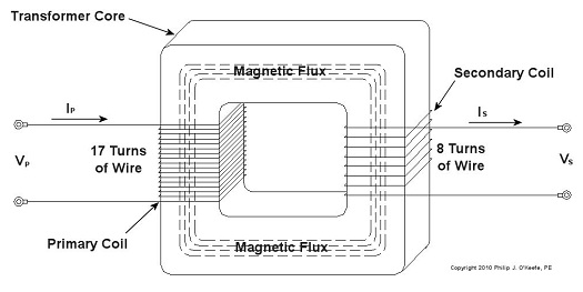
Figure 2 – Basic Transformer Example We can see that the primary coil has 17 turns of wire and the secondary coil has 8. For purposes of our example and to keep the numbers workable, let’s arbitrarily say that VP = 5 volts AC. By the way, the power initially coming into the transformer feeding your home is typically measured in the thousands of volts. Now it’s time to do some math. Based on this input voltage and the number of wire turns in each coil, what would the voltage be on the secondary coil? As William Stanley discovered, it’s a matter of ratios and algebra, and it works according to this formula: NP ÷ NS = VP ÷ VS Here NP and NS are the number of turns of wire in the primary and secondary coils, respectively. So plugging in the numbers we get: 17 turns ÷ 8 turns = 5 volts ÷ VS [(8 turns ÷ 17 turns) x 5 volts] = VS = 2.3 volts This tells us that the transformer in our example reduces, or “steps down” 5 volts AC to just under half the voltage. So the transformer changed a higher voltage to a lower voltage. By the same token, a large utility transformer can be used to reduce transmission line voltage to one which can be used safely within our homes. Like magic, this mechanism also works in reverse. For example, you can apply 2.3volts AC to the 8 turn coil and you will get 5 volts AC out of the 17 turn coil, resulting in a “stepping up” of voltage. But wait a minute. How can you possibly get more voltage out than you put in? Next time we’ll find out. _____________________________________________
|
Posts Tagged ‘alternating current’
Transformers – Something To Do With The Flux
Sunday, December 19th, 2010
Transformers – Alternating Current Does the Trick
Sunday, December 12th, 2010| If you’ve seen the movie The Prestige, you know just how “tricky” electricity can be, and if you haven’t seen it yet, you’ve yet to see a great movie. In it, Hugh Jackman uses the magical properties of electricity to pull off a magic trick the likes of which the world has never seen. But that’s all I’ll say about that… see the movie.
In 1886, a young American inventor named William Stanley did some serious thinking about Michael Faraday, the British scientist we introduced last week, and his work with electricity and magnetism. Stanley figured out how to put it all together. The result was the world’s first electrical transformer. What fueled Stanley’s curiosity? Like most good inventors, he perceived a need and sought to fill it. At the time George Westinghouse was developing his alternating current (AC) electric utility power system, the same basic system we use today. As Westinghouse’s chief engineer, Stanley was given the task of figuring out a way to efficiently change voltage levels on an AC power grid. The industrial revolution was in full swing, and for various industrial purposes factories needed to operate on voltage levels different from those produced by the Westinghouse generators. Stanley approached the task before him with the benefit of knowledge supplied by Faraday’s experimentation. He knew that Faraday was able to cause current to flow through a wire by moving a magnet near it back and forth. This phenomenon occurred because lines of magnetic flux were varying over time with respect to the wire through the magnet’s movement. Being aware of the vicissitudes of alternating current, the way it varies in intensity and direction, Stanley was able to conclude that any lines of magnetic flux generated by AC current flowing through a coiled wire would also tend to vary over time. Armed with this knowledge, Stanley replaced the DC battery used in Faraday’s experiment with an AC generator. This modified setup is shown in Figure 1.
Figure 1 – Faraday’s Experiment Modified With An AC Power Source In the modified setup the switch is closed, causing the AC power flowing through the first coiled wire to create lines of magnetic flux in the iron rod. These lines of flux continually vary and thus induce AC flow in the second coil. The action taking place is duly recorded by a Galvanometer needle, which keeps moving so long as the switch remains closed. Stanley also knew that the voltage created in the second coiled wire was dependent on how many turns, or loops, of wire were present in it compared to the number of turns of wire in the first coil. He made the observation that if less turns were present in the second coiled wire as compared to the first, less voltage would also be emitted from the second coiled wire. This demonstrates the phenomenon of changing voltage with respect to supply delivered by the AC generator to the first coil. Putting these findings together, Stanley was able to develop the first practical electrical transformer, whose basic design is shown in Figure 2. Here we see that the iron rod from Faraday’s experiment has been replaced with an iron transformer core resembling a squared off doughnut.
Figure 2 – A Basic Electrical Transformer Next time we’ll get into the math behind this discussion, and we’ll see how Stanley’s transformer worked. _____________________________________________ |


