Posts Tagged ‘beam’

The Math Behind a Static Compound Pulley

Friday, September 9th, 2016

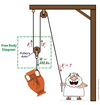
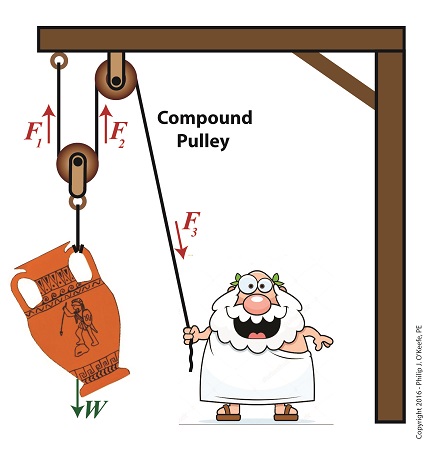
    Last time we introduced the compound pulley and saw how it improved upon a simple pulley, both of which I’ve engaged in my work as an engineering expert.  Today we’ll examine the math behind the compound pulley.   We’ll begin with a static representation and follow up with an active one in our next blog.

    The compound pulley illustrated below contains three rope sections with three representative tension forces, F1, F2, and F3.   Together, these three forces work to offset the weight, W, of a suspended urn weighing 40 lbs.   Weight itself is a downward pulling force due to the effects of gravity.

    To determine how our pulley scenario affects the man holding his section of rope and exerting force F3, we must first calculate the tension forces F1 and F2.   To do so, we’ll use a free body diagram, shown in the green box, to display the forces’ relationship to one another.

A Compound Pulley

The Math Behind a Static Compound Pulley

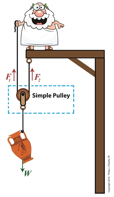
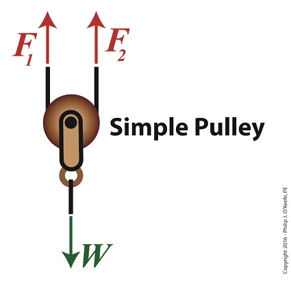
    The free body diagram only takes into consideration the forces inside the green box, namely F1, F2, and W.

    For the urn to remain suspended stationary in space, we know that F1 and F2 are each equal to one half the urn’s weight, because they’re spaced equidistant from the pulley’s axle, which directly supports the weight of the urn.  Mathematically this looks like,

F1 = F2 = W ÷ 2

    Because we know F1 and F2, we also know the value of F3, thanks to an engineering rule concerning pulleys.  That is, when a single rope is used to support an object with pulleys, the tension force in each section of rope must be equal along the entire length of the rope, which means F1 = F2 = F3.    This rule holds true whether the rope is threaded through one simple pulley or a complex array of fixed and moveable simple pulleys within a compound pulley.   If it wasn’t true, then unequal tension along the rope sections would result in some sections being taut and others limp, which would result in a situation which would not make lifting the urn any easier and thereby defeat the purpose of using pulleys.

    If the urn’s weight, W, is 40 pounds, then according to the aforementioned engineering rule,

F1 = F2 = F3= W ÷ 2

F1 = F2 = F3 =  (40 pounds) ÷ 2 = 20 pounds

    Mr. Toga needs to exert a mere 20 pounds of personal effort to keep the immobile urn suspended above the ground.   It’s the same effort he exerted when using the improved simple pulley in a previous blog, but this time he can do it from the comfort and safety of standing on the ground.

    Next time we’ll examine the math and mechanics behind an active compound pulley and see how movement affects F1 , F2 , and F3.


Copyright 2016 – Philip J. O’Keefe, PE

Engineering Expert Witness Blog

____________________________________


The Compound Pulley

Saturday, August 13th, 2016

    Sometimes one of something just isn’t enough, like one potato chip, one glass of wine… And when it comes to lifting massive objects one simple pulley isn’t going to be enough to get the job done.   Even the improved simple pulley, which we introduced last week, is often not enough, a situation which I’ve run across in my career as an engineering expert.   To get past the limitations of the simple pulley and improved simple pulley, ancient Greeks went on to devise the compound pulley, which we’ll introduce today.

The Compound Pulley

The Compound Pulley


    A compound pulley, such as the one shown here, consists of two or more simple pulleys. In the compound pulley system, a combination of fixed and moveable simple pulleys are used to lift objects.   The scenario shown in our illustration features a compound pulley consisting of two simple pulleys, one is stationary and affixed to a beam, the other hangs freely in space, riding on the rope connecting them.   One end of the rope is held by Mr. Toga, the other end is affixed to the beam.   In fact, all compound pulleys require that at least one simple pulley be affixed to a stationary structure, and at least one other simple pulley must be free to move in space.

    When our toga clad friend pulls his end of the rope he exerts a force, F3, via the pulley affixed to the beam.   This force transmits on to the pulley attached to the urn, which results in lifting the urn off the ground.

    Next week we’ll calculate the force on Mr. Toga’s end, F3, as well as the other forces at play, F1 and F2.

Copyright 2016 – Philip J. O’Keefe, PE

Engineering Expert Witness Blog

____________________________________


Using a Free Body Diagram to Understand Simple Pulleys

Thursday, July 21st, 2016

    Sometimes the simplest alteration in design results in a huge improvement, a truth I’ve discovered more than a few times during my years as an engineering expert.   Last time we introduced the simple pulley and revealed that its usefulness was limited to the strength of the pulling force behind it.   Hundreds of years ago that force was most often supplied by a man and his biceps.   But ancient Greeks found an ingenious and simple way around this limitation, which we’ll highlight today by way of a modern design engineer’s tool, the free body diagram.

    Around 400 BC, the Greeks noticed that if they detached the simple pulley from the beam it was affixed to in our last blog and instead allowed it to be suspended in space with one of its rope ends fastened to a beam, the other rope end to a pulling force, something interesting happened.

The Simple Pulley Improved

The Simple Pulley Improved

    It was much easier to lift objects while suspended in air.  As a matter of fact, it took 50% less effort.   To understand why, let’s examine what engineers call a free body diagram of the pulley in our application, as shown in the blue inset box and in greater detail below.

Free Body Diagram of an Improved Simple Pulley

Using a Free Body Diagram to Understand Simple Pulleys

    The blue insert box in the first illustration highlights the subject at hand.   A free body diagram helps engineers analyze forces acting upon a stationary object suspended in space.   The forces acting upon the object, in our case a simple pulley, represent both positive and negative values.   The free body diagram above indicates that forces pointing up are, by engineering convention, considered to be positive, while downward forces are negative.   The basic rule of all free body diagrams is that in order for an object to remain suspended in a fixed position in space, the sum of all forces acting upon it must equal zero.

    We’ll see how the free body diagram concept is instrumental in understanding the improvement upon the action of a simple pulley next time, when we attack the math behind it.

Copyright 2016 – Philip J. O’Keefe, PE

Engineering Expert Witness Blog

____________________________________