|
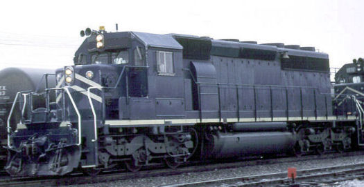
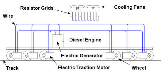
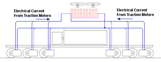
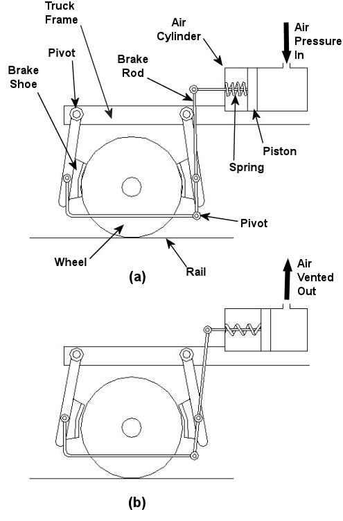
In the past few weeks we’ve taken a look at both mechanical and dynamic brakes. Now it’s time to bring the two together for unparalleled stopping performance. Have you ever wandered along a railroad track, hopping from tie to tie, daring a train to come roaring along and wondering if you could jump to safety in time? Many have, and many have lost the bet. That’s because a train, once set into motion, is one of the hardest things on Earth to bring to a stop. In this discussion, let’s focus on the locomotive. A large, six-axle variety is shown in Figure 1. Figure 1 – A Six-Axle Diesel-Electric Locomotive These massive iron horses are known in the industry as diesel-electric locomotives, and here’s why. As Figure 2 shows, diesel-electric locomotives are powered by huge diesel engines. Their engine spins an electrical generator which effectively converts mechanical energy into electrical energy. That electrical energy is then sent from the generator through wires to electric traction motors which are in turn connected to the locomotive’s wheels by a series of gears. In the case of a six-axle locomotive, there are six traction motors all working together to make the locomotive move. So how do you get this beast to stop? Figure 2 – The Propulsion System In A Six-Axle Diesel-Electric Locomotive You probably noticed in Figure 2 that there are resistor grids and cooling fans. As long as you’re powering a locomotive’s traction motors to move a train, these grids and fans won’t come into play. It’s when you want to stop the train that they become important. That’s when the locomotive’s controls will act to disconnect the traction motor wires running from the electrical generator and reconnect them to the resistor grids as shown in Figure 3 below. Figure 3 – The Dynamic Braking System In A Six-Axle Diesel Electric Locomotive The traction motors now become generators in a dynamic braking system. These motors take on the properties of a generator, converting the moving train’s mechanical, or kinetic, energy into electrical. The electrical energy is then moved by wires to the resistor grids where it is converted to heat energy. This heat energy is removed by powerful cooling fans and released into the atmosphere. In the process the train is robbed of its kinetic energy, causing it to slow down. Now you may be thinking that dynamic brakes do all the work, and this is pretty much true, up to a point. Although dynamic brakes may be extremely effective in slowing a fast-moving train, they become increasingly ineffective as the train’s speed decreases. That’s because as speed decreases, the traction motors spin more slowly, and they convert less kinetic energy into electrical energy. In fact, below speeds of about 10 miles per hour dynamic brakes are essentially useless. It is at this point that the mechanical braking system comes into play to bring the train to a complete stop. Let’s see how this switch from dynamic to mechanical dominance takes place. A basic mechanical braking system for locomotive wheels is shown in Figure 4. This system, also known as a pneumatic braking system, is powered by compressed air that is produced by the locomotive’s air pump. A similar system is used in the train’s railcars, employing hoses to move the compressed air from the locomotive to each car. Figure 4 – Locomotive Pneumatic Braking System In the locomotive pneumatic braking system, pressurized air enters an air cylinder. Once inside, the air bears against a spring-loaded piston, as shown in Figure 4(a). The piston moves, causing brake rods to pivot and clamp the brake shoes to the locomotive’s wheel with great force, slowing the locomotive. When you want to get the locomotive moving again, you vent the air out of the cylinder as shown in Figure 4(b). This takes the pressure off the piston, releasing the force from the brake shoes. The spring in the cylinder is now free to move the shoes away from the wheel so they can turn freely. We have now returned to the situation present in Figure 2, and the locomotive starts moving again. Next week we’ll talk about regenerative braking, a variation on the dynamic braking concept used in railway vehicles like electric locomotives and subway trains. _____________________________________________ |
Engineering Expert Witness Blog
Published by Philip J. O'Keefe, PE, MLE
