Posts Tagged ‘centrifugal pump’
Monday, May 21st, 2018
|
We couldn’t do without pumps. They serve up water from the tap, circulate our car’s coolant, and the master of all pumps, the human heart, keeps us alive. Pumps are essential in countless areas of our lives, and they’re of two major types, positive displacement or centrifugal. We’ll start our discussion with a focus on positive displacement pumps. Our hearts belong to this category.
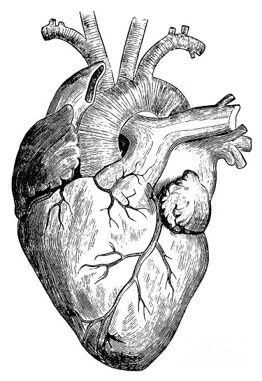
Master of All Pumps, the Human Heart
As their name implies, positive displacement pumps displace, that is to say they move or circulate, a set quantity of liquid with each operating cycle. Your heart moves 2 to 3 ounces of blood with every heartbeat and up to 2,000 gallons of blood per day!
Next week we’ll introduce an industrial application for a positive displacement pump when we install one in a food manufacturing plant. You didn’t think those jelly pastries filled themselves, did you?
Copyright 2018 – Philip J. O’Keefe, PE
Engineering Expert Witness Blog
____________________________________ |
Tags: centrifugal pump, food manufacturing, positive displacement pump
Posted in Engineering and Science, Expert Witness, Forensic Engineering, Innovation and Intellectual Property, Personal Injury, Product Liability | Comments Off on Master of All Pumps, the Human Heart
Monday, May 14th, 2018
|
In our last article, we looked at an example problem involving a cavitating centrifugal pump that was drawing water from a storage tank. The bottom of the storage tank was sitting at the same level as the centrifugal pump’s inlet. The water level in the tank could not be increased to raise the pump inlet pressure, and thus eliminate the cavitation. So, the problem was solved by elevating the tank with respect to the pump inlet. Okay, what if the tank could not be elevated? How do we stop the centrifugal pump from cavitating? Well, we can install a booster pump between the tank and the centrifugal pump.
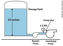
A booster pump is, as its name implies, a special kind of pump that is used to boost, or raise, water pressure flowing in a pipe. With regard to our example problem in the preceding article, the cavitating centrifugal pump inlet water is at 108ºF and a pressure of 1.2 pounds per square inch (PSI).

Reducing Cavitation With A Booster Pump — Before
Referring to the thermodynamic properties of water as found in tables appearing in engineering texts, we determine that if we keep water temperature at 108ºF but raise the pressure at the pump inlet from 1.2 PSI to 1.5 PSI we can stop the centrifugal pump from cavitating. We can install a booster pump to boost the pressure by the required 0.3 PSI and say goodbye to our cavitation problems.
Reducing Cavitation With A Booster Pump — After
This wraps it up for our series on cavitation in pumps. Next time, we’ll begin learning about some different topics.
Copyright 2018 – Philip J. O’Keefe, PE
Engineering Expert Witness Blog
____________________________________ |
Tags: booster pump, cavitation, centrifugal pump, engineering, pump inlet pressure, thermodynamics, water pressure, water tank elevation, water tank level, water temperature
Posted in Engineering and Science, Expert Witness, Forensic Engineering, Innovation and Intellectual Property, Personal Injury, power plant training, Product Liability | Comments Off on Reducing Cavitation With A Booster Pump
Monday, May 7th, 2018
|
Last time we learned that the risk of damaging cavitation bubbles forming at a centrifugal pump’s inlet can be eliminated by simply increasing the water level inside the tank. Today we’ll do the math that demonstrates how reducing cavitation can be accomplished by raising tank elevation.
Reducing Cavitation by Raising Tank Elevation–Before
In our example we’ll suppose that we’re having a problem with cavitation bubbles forming at the inlet, where water temperature is 108ºF and water level inside the tank stands at 33 inches. We are using the formula,
P = γ × h (1)
Equation (1) was introduced previously to correlate water pressure, P, with the specific weight of water, (0.036 pounds/inch3), and the height, h, of the water surface in the tank. If h is 33 inches, then we obtain,
P = (0.036 pounds/inch3) × (33 inches) = 1.2 pounds/inch2 (2)
So, the weight of the water in the tank exerts a pressure of 1.2 pounds per square inch (PSI) at the bottom of the tank and the pump inlet when it sits at the same elevation as the tank.
We know that if we increase the water depth in the tank relative to the pump inlet, we can raise the pressure at the pump inlet in accordance with equation (1). Raising the pressure will eliminate the cavitation bubbles that can form there. But, our tank is of fixed volume, and we can’t add more water to raise water depth beyond 33 inches. However, we can increase the elevation of the tank with respect to the inlet, which will produce the same effect. We’ll use equation (1) to determine the tank elevation, h, that will provide the needed increase.
Referring to the thermodynamic properties of water as found in tables appearing in engineering texts, we determine that if we keep water temperature at 108ºF but raise the pressure at the pump inlet from 1.2 PSI to 1.5 PSI, while maintaining current water depth in the tank, cavitation will cease. In other words, we need to increase P by 0.3 PSI.
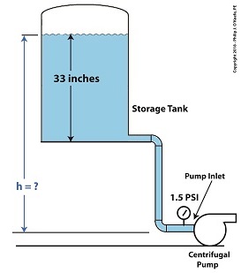
Example of Reducing Cavitation by Tank Elevation–After
Plugging our known values into equation (1) we solve for h,
0.3 PSI = 0.036 pounds/inch3 × h (3)
h = 0.3 PSI ÷ 0.036 pounds/inch3 (4)
h = 8.3 inches (5)
Cavitation will cease when we elevate the tank by 8.3 inches with respect to the pump.
Yet another means of increasing inlet pressure is to install a booster pump. We’ll talk about that next time.
Copyright 2018 – Philip J. O’Keefe, PE
Engineering Expert Witness Blog
____________________________________
|
Tags: cavitation, centrifugal pump, engineering, pump inlet, specific weight of water, stopping cavitation, thermodynamics, water depth, water pressure, water tank elevation
Posted in Engineering and Science, Expert Witness, Forensic Engineering, Innovation and Intellectual Property, power plant training, Product Liability, Professional Malpractice | Comments Off on Reducing Cavitation by Raising Tank Elevation
Monday, April 16th, 2018
|
Ever hear the old saying, “There’s more than one way to cook a goose”? The statement is meant to encourage creative thinking when problem solving. This forward thinking can be applied to the problem of destructive cavitation bubbles as well. Finding ways to reduce cavitation is something engineers are well versed in. As discussed in our last blog, one way to prevent cavitation is by lowering water temperature at a centrifugal pump’s inlet. But sometimes that isn’t possible. Today we’ll discuss another way, reducing cavitation by increasing water pressure.
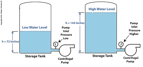
One way to Reduce Cavitation by Increasing Water Pressure
If you’ve ever seen a movie featuring divers, you’ll no doubt be aware that the deeper a diver goes, the more water pressure there is bearing down on him from above. The same goes for a centrifugal pump’s storage tank. The higher the water level inside the tank, the higher the pressure bearing down on the pump’s inlet, which is located at the bottom of the tank. This is the area in which cavitation bubbles are likely to form. The mathematical equation that illustrates this relationship is,
P = γ × h (1)
where, P is water pressure at the bottom of the tank, γ is the Greek symbol gamma, representing the specific weight of water, (0.036 pounds/inch3), and h is the depth of the water inside the tank.
Let’s see what happens when we increase the water level, h, from 72 inches, shown on the left, to 144 inches, on the right.
P = (0.036 Lb/in3) × (72 in) = 2.592 PSI (2)
When the water level is raised to 144 inches, P becomes,
P = (0.036 Lb/in3) × (144 in) = 5.184 PSI (3)
We see that by raising the water level in the tank from 72 to 144 inches, pressure at the bottom of the tank where the inlet is located is increased from 2.592 PSI to 5.184 PSI, pounds per square inch.
Next time we’ll see how simply elevating the tank has an impact on cavitation.
Copyright 2018 – Philip J. O’Keefe, PE
Engineering Expert Witness Blog
____________________________________ |
Tags: cavitation, cavitation bubbles, centrifugal pump, engineering, pressure, pump inlet, specific weight of water, storage tank, temperature, water level
Posted in Engineering and Science, Expert Witness, Forensic Engineering, Innovation and Intellectual Property, Personal Injury, power plant training, Product Liability | Comments Off on One way to Reduce Cavitation by Increasing Water Pressure
Monday, April 9th, 2018
|
As we learned previously, cavitation bubbles form at a centrifugal pump’s inlet when the thermodynamic properties of water, namely temperature and pressure, are right. Today we’ll see how just manipulating water temperature can control cavitation.

Manipulating Water Temperature to Control Cavitation
Some centrifugal pumps draw water from an external heat source such as a heat exchanger in order to provide heat to buildings, generate power, and perform manufacturing processes. On some exchangers heat is applied at a fixed rate and can’t be varied. On others heat can be varied by using a heat exchanger fitted with a temperature control. This makes it easy to reduce or lower water temperature introduced at the pump’s inlet. If the temperature is kept low enough relative to the pressure at the inlet, cavitation bubbles won’t form.
Let’s say water enters the pump’s inlet from a heat exchanger at 59ºF and internal pump pressure is 0.25 pounds per square inch (PSI). With these parameters in place water boils and cavitation bubbles will form in the pump inlet. But if the heat exchanger is adjusted so that temperature is lowered by a mere two degrees to 57ºF, cavitation ceases. This is in accordance with the boiling points of water, listed for various pressures and temperatures, as published in engineering thermodynamic texts.
If it’s not possible to lower water temperature at the pump inlet, an alternate method to control cavitation is to raise water pressure, which can be accomplished in different ways. We’ll review those options next time.
Copyright 2018 – Philip J. O’Keefe, PE
Engineering Expert Witness Blog
____________________________________ |
Tags: cavitation, centrifugal pump, engineering, heat exchanger, pressure, temperature, temperature control, thermodynamics
Posted in Engineering and Science, Expert Witness, Forensic Engineering, Innovation and Intellectual Property, Personal Injury, power plant training, Product Liability | Comments Off on Manipulating Water Temperature to Control Cavitation
Monday, April 2nd, 2018
|
Last time we learned how cavitation degrades a centrifugal pump’s performance by restricting and reducing the water flow at the pump’s inlet where these destructive bubbles are formed. Today we’ll see that despite the fact these cavitation bubbles return to a liquid water state further along in the pump’s high pressure section when they implode, the water flow within the pump remains the same. This is true because of the engineering principle of continuity, which holds that the water flow rate within a pump or any other closed system remains the same throughout that system. What goes in must come out.
Continuity has to do with the rate of water flowing through pipes, valves, and pumps within a plumbing system. As water flows through a centrifugal pump, its flow rate is measured as the volume of water that moves past a certain point in the pump per unit of time. Suppose for example that during one minute of elapsed time the volume of water flowing through at the inlet point is found to be five gallons. This then becomes the system’s flow rate of 5 gallons per minute. We’ll call this flow rate Q1.
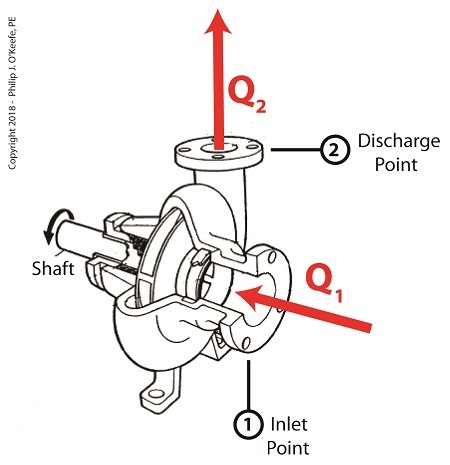
The Principle of Continuity – What Goes In Must Come Out
The principle of continuity states that this flow rate Q1 must remain the same throughout the pump. If this were not true, any observed difference in water volume would mean water is somehow either lost or created between the pump’s inlet and discharge. This is an impossibility if the pump is an intact enclosed system, absent any other inlet points or leaks. So according to the principle of continuity, Q1 must equal Q2, the flow rate at pump discharge.
When cavitation occurs at the pump’s inlet, Q1, these steam bubbles restrict water flowing into the pump. Although these bubbles will later implode and return to a liquid water state further along the pump system, this change will not affect the flow rate of the water within the pump. The flow rate established at intake will remain the same at pump discharge, Q2.
Next time we’ll see how cavitation in centrifugal pumps can be prevented.
Copyright 2018 – Philip J. O’Keefe, PE
Engineering Expert Witness Blog
____________________________________ |
Tags: cavitation, centrifugal pump, continuity, flow rate, gallons per minute, plumbing, pump performance, valves
Posted in Engineering and Science, Expert Witness, Forensic Engineering, Innovation and Intellectual Property, Personal Injury, power plant training, Product Liability | Comments Off on The Principle of Continuity – What Goes In Must Come Out
Sunday, March 25th, 2018
|
Previously we learned how cavitation bubbles cause noise, vibration, and damage to centrifugal pumps. Today we’ll see how cavitation bubbles degrade pump performance in a centrifugal pump’s low pressure section.
Cavitation Bubbles Degrade Pump Performance
During cavitation multitudes of tiny steam bubbles form and become suspended in the water that’s constantly flowing through a working centrifugal pump. These bubbles decrease the density of the water because steam bubbles are lighter and occupy less space than liquid water. This decrease in the water’s density causes the pump to be less efficient, because for any given amount of horsepower that’s conveyed to the pump’s impeller by an external power source, the pump’s ability to promote water discharge is compromised due to the bubbles.
As an example, let’s say that when the bubbles of cavitation form inside a pump, the pump’s water-bubble ratio is a mixture of 70 percent liquid water and 30 percent steam bubbles. That’s a lot of bubbles, and they act to restrict water flowing through the pump’s inlet, reducing flow rate by 30 percent.
As water moves from the inlet towards the spinning impeller, all the steam bubbles implode in on themselves in the high pressure section of the pump. They return once again to their liquid state and join the rest of the water flowing towards pump discharge, but despite this the pump’s flow rate remains reduced at the discharge.
We’ll find out why this is true next time when we discuss the engineering principle of continuity.
opyright 2018 – Philip J. O’Keefe, PE
Engineering Expert Witness Blog
____________________________________ |
Tags: cavitation, centrifugal pump, continuity, pump performance, steam bubbles, water density
Posted in Engineering and Science, Expert Witness, Forensic Engineering, Innovation and Intellectual Property, Personal Injury, power plant training, Product Liability | Comments Off on Cavitation Bubbles Degrade Pump Performance
Monday, March 12th, 2018
|
Last time we learned how both low and high pressures exist within a single centrifugal pump, and if water pressure at the inlet is low enough, the cavitation process begins. Today we’ll see how these rapidly imploding water vapor bubbles create serious problems in the pump’s high pressure area.
Rapidly Imploding Bubbles Create Problems
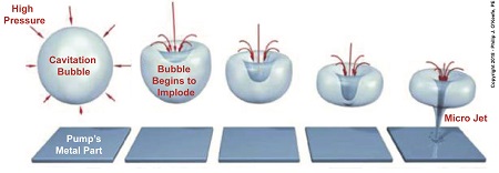
Water flows from low pressure at a centrifugal pump’s inlet to high pressure upstream when it meets up with the pump’s impeller. This high pressure causes cavitation bubbles formed at the inlet to rapidly implode, that is, collapse in on themselves. Implosion occurs because pressure outside the bubbles is much greater than the pressure inside them. This pressure difference exists because the bubbles were formed in the low pressure area of the pump.
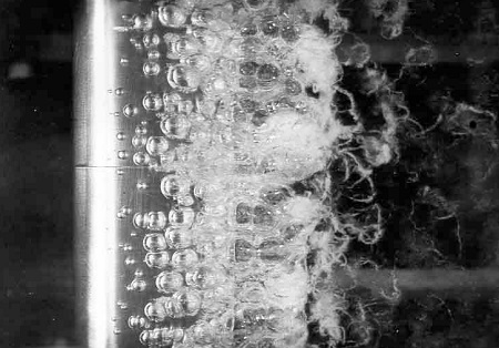
When cavitation bubbles meet up with high pressure areas deep inside the pump, they get squeezed hard and burst rapidly, creating multitudes of shock waves, grinding noise, and vibration so intense it sounds as though gravel, not steam bubbles, are passing through the pump. The noise and vibration are bad enough, but cavitation has far worse consequences.
Rapidly imploding bubbles form tiny but powerful micro jets of water which hold an enormous amount of kinetic energy. When these jets hit the pump’s metal interior, their kinetic energy causes minute fragments of metal to break away. Over time these tiny water jets wear away enough metal to cause damage to the pump’s interior and interfere with function.
Next time we’ll see how cavitation bubbles flowing through the low pressure area of a pump degrade its performance.
opyright 2018 – Philip J. O’Keefe, PE
Engineering Expert Witness Blog
____________________________________ |
Tags: cavitation, cavitation bubbles imploding, centrifugal pump, micro jet, noise, pump high pressure area, pump low pressure area, shock waves, vibration
Posted in Engineering and Science, Expert Witness, Forensic Engineering, Innovation and Intellectual Property, Personal Injury, power plant training, Product Liability | Comments Off on Rapidly Imploding Bubbles Create Problems
Friday, March 2nd, 2018
|
Last time we discussed how the curved features of a centrifugal pump are key to its functionality. Today we’ll examine a centrifugal pump’s impeller action and see how it creates a volatile environment inside the pump in which cavitation bubbles flourish.

Centrifugal Pump Impeller Action
Inside a centrifugal pump both low and high pressure areas are created, chiefly due to the action of the pump’s spinning impeller. Low pressure is created at the water inlet in a way very similar to what happens when you pull the plug on your bathtub. With the plug removed the drain opens and a tiny whirlpool forms, causing water to get sucked into the plumbing for discharge.
The same thing happens inside a centrifugal pump due to tumultuous internal water movement. The spinning impeller vigorously moves water from inlet to discharge. As water is discharged, a void, or vacuum, is created inside the pump, causing water at the inlet to get sucked inside at low pressure, very much like when you suck liquid through a straw.
As water moves inside the housing, it comes into contact with the rotating impeller itself. This impeller is comprised of multiple spiral curved blades with a volute shape, made to maximize efficient movement of water. They use the power of centrifugal force to create a high pressure environment, and water is flung at high speed towards the pump’s outlet, where it is then discharged.
Next time we’ll see how the coexistence of low and high pressures within the centrifugal pump housing create the problem of cavitation bubbles.
opyright 2018 – Philip J. O’Keefe, PE
Engineering Expert Witness Blog
____________________________________ |
Tags: cavitation bubbles, centrifugal pump, discharge, impeller, impeller blades, inlet, volute
Posted in Engineering and Science, Expert Witness, Forensic Engineering, Innovation and Intellectual Property, Personal Injury, Product Liability | Comments Off on Centrifugal Pump Impeller Action
Wednesday, February 21st, 2018
|
Last time we learned how centrifugal pumps can create a low pressure environment at the pump’s inlet, which can allow water inside the pump to boil at temperatures far lower than normal. Ultimately, this results in the formation of tiny but destructive cavitation bubbles. Today we’ll see how a centrifugal pump’s curved features are key to its functionality.
A Centrifugal Pump’s Curved Features are Key to Functionality
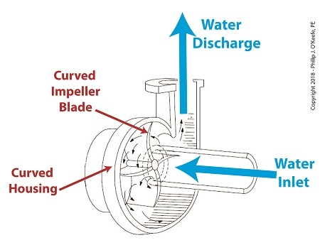
Even a casual glance at a centrifugal pump will disclose its many curved features. As the illustration shows, both the housing and internal impeller blades, are curved. These curves are known as volutes. The volutes’ dimensions are mathematically generated by engineers to facilitate the precise flow of water from inlet to discharge by way of the pump’s impeller blades.
Next time we’ll see how a centrifugal pump is home to both low and high water pressure, creating a volatile environment in which cavitation bubbles form and collapse.
opyright 2018 – Philip J. O’Keefe, PE
Engineering Expert Witness Blog
____________________________________ |
Tags: cavitation, centrifugal pump, engineering, flow, housing, impeller blades, volute
Posted in Engineering and Science, Expert Witness, Forensic Engineering, Innovation and Intellectual Property, Personal Injury, power plant training, Product Liability | Comments Off on A Centrifugal Pump’s Curved Features are Key to Functionality


