|
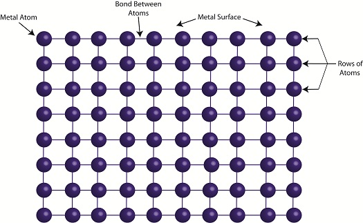
When I’m under a lot of stress I sometimes have the nervous habit of grabbing a paper clip, straightening out the bends, then repetitively bending it back and forth. Eventually the wire reaches a point where it just breaks apart. My paper clip broke due to metal fatigue. Metal parts are said to become fatigued when they’re subjected to forces of a repetitive nature such as occur due to twisting and bending. The metal cracks, then eventually breaks due to the stress. So what’s happening when metal becomes fatigued? Figure 1 shows the simplified atomic structure of a sample metal. Figure 1
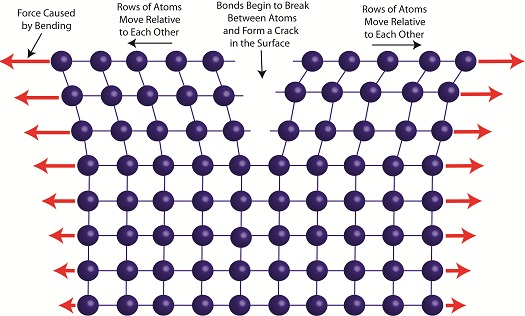
When the metal is deformed, such as during bending, its rows of atoms are forced to move with respect to each other as shown in Figure 2.
Figure 2
The movement of rows of atoms leads to an alteration in structure, breaking bonds between atoms. This results in small cracks forming along the metal’s surface, cracks which eventually migrate deeper inside the metal with each subsequent bend. With time the metal will become so compromised by the cracks that breakage occurs. Metal fatigue can occur in centrifugal clutch mechanisms as well. Power tools such as grass trimmers typically operate between idle and working speeds many times during a day’s usage. As we learned in previous articles, when the engine runs at idle speed, the springs in the centrifugal clutch mechanism stay retracted. As the engine speeds up, the centrifugal force acting on the clutch shoes extends the springs. Successive extensions and retractions cause the metal in the springs to bend, and over time they, like my paper clip, will become fatigued and metal springs will break. Next time we’ll continue talking about centrifugal clutch failures and learn how the springs of a clutch mechanism can fail without its metal being brought to the breaking point.
____________________________________________
|
Posts Tagged ‘clutch boss’
Mechanical Power Transmission – The Centrifugal Clutch in Operation
Sunday, April 22nd, 2012| Just the other day I unexpectedly experienced the effects of centrifugal force while driving home from the grocery store. The checker had packed my entire order into one bag, making it top heavy. Then en route someone cut me off at an intersection, and I had to make a sharp turn to avoid a crash. During this maneuver centrifugal force came into play, forcing my grocery bag out of its centered position on the front seat next to me. It lurched into the passenger’s door, fell over, and spilled its contents onto the floor. Fortunately the eggs didn’t get smashed.
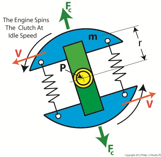
In previous articles we identified the component parts of a centrifugal clutch mechanism and learned how centrifugal force makes objects spinning in a circular path about a fixed point move outward. We can now explore what happens when we couple a centrifugal clutch mechanism to the engine of a grass trimmer. Figure 1 depicts the spinning clutch mechanism of a gas engine when it’s just been started and is operating at a slow idle speed. Figure 1
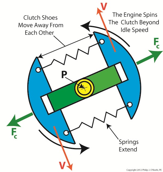
Like the red ball in my previous article on centrifugal force, the blue centrifugal clutch shoes each have a mass m. They spin around a fixed point P, situated at the center of the yellow engine shaft coupling. Point P is located a distance r from the center of each shoe. The shoes in motion have a tangential velocity V, and in accordance with Sir Isaac Newton’s Law of Centrifugal Force, the force Fc acts upon each shoe, causing them to want to pull out from the center of the mechanism, away from the fixed point. Since idle speed is rather slow, however, the centrifugal force exerted upon the shoes isn’t strong enough to overcome the tension of the two springs and the coils connecting them remain coiled, holding the shoes tightly in position on the green boss. So what happens when we press the throttle trigger on the gas engine and cause the engine to speed up? See Figure 2. Figure 2
Figure 2 shows the clutch mechanism spinning at an increased velocity. The tangential velocity V increases, and according to Newton’s law, the centrifugal force Fc acting on the clutch shoes increases as well. The force is so strong that it overcomes the tension in the springs and they extend. The clutch shoes are caused to move out and away from fixed point P, as well as from each other, traveling along the ends of the boss. When we remove our finger from the throttle trigger, the engine will slow down and return to idle speed. The centrifugal force will decrease and the springs will pull the shoes back towards fixed point P. The mechanism will return to its previous state, as shown in Figure 1. Next time we’ll insert the centrifugal clutch mechanism into the clutch housing to see how mechanical power is transmitted from the engine to the cutter head in our grass trimmer. ____________________________________________
|


