Posts Tagged ‘compound pulley’
Tuesday, February 28th, 2017
|
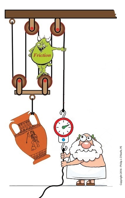
For some time now we’ve been analyzing the helpfulness of the engineering phenomena known as pulleys and we’ve learned that, yes, they can be very helpful, although they do have their limitations. One of those ever-present limitations is due to the inevitable presence of friction between moving parts. Like an unsummoned gremlin, friction will be standing by in any mechanical situation to put the wrench in the works. Today we’ll calculate just how much friction is present within the example compound pulley we’ve been working with.
So How Much Friction is Present in our Compound Pulley?
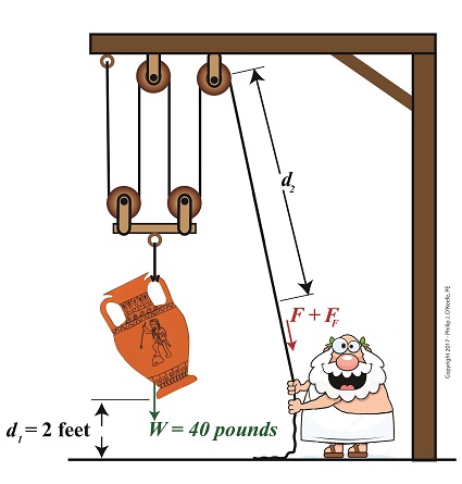
Last time we began our numerical demonstration of the inequality between a compound pulley’s work input, WI, and work output, WO, an inequality that’s due to friction in its wheels. We began things by examining a friction-free scenario and discovered that to lift an urn with a weight, W, of 40 pounds a distance, d1, of 2 feet above the ground, Mr. Toga exerts a personal effort/force, F, of 10 pounds to extract a length of rope, d2, of 8 feet.
In reality our compound pulley must contend with the effects of friction, so we know it will take more than 10 pounds of force to lift the urn, a resistance which we’ll notate FF. To determine this value we’ll attach a spring scale to Mr. Toga’s end of the rope and measure his actual lifting force, FActual, represented by the formula,
FActual = F + FF (1)
We find that FActual equals 12 pounds. Thus our equation becomes,
12 Lbs = 10 Lbs + FF (2)
which simplifies to,
2 Lbs = FF (3)
Now that we’ve determined values for all operating variables, we can solve for work input and then contrast our finding with work output,
WI = (F × d2) + (FF × d2) (4)
WI = (10 Lbs × 8 feet) + (2 Lbs × 8 feet) (5)
WI = 96 Ft-Lbs (6)
We previously calculated work output, WO to be 80 Ft-Lbs, so we’re now in a position to calculate the difference between work input and work output to be,
WI – WO = 16 Ft-Lbs (7)
It’s evident that the amount of work Mr. Toga puts into lifting his urn requires 16 more Foot-Pounds of work input effort than the amount of work output produced. This extra effort that’s required to overcome the pulley’s friction is the same as the work required to carry a weight of one pound a distance of 16 feet. We can thus conclude that work input does not equal work output in a compound pulley.
Next time we’ll take a look at a different use for pulleys beyond that of just lifting objects.
Copyright 2017 – Philip J. O’Keefe, PE
Engineering Expert Witness Blog
____________________________________ |
Tags: compound pulley, engineering, friction, pulley, work, work input, work output
Posted in Engineering and Science, Expert Witness, Forensic Engineering, Innovation and Intellectual Property, Personal Injury, Product Liability | Comments Off on So How Much Friction is Present in our Compound Pulley?
Wednesday, February 15th, 2017
|
Last time we began work on a numerical demonstration and engineering analysis of the inequality of work input and output as experienced by our example persona, an ancient Greek lifting an urn. Today we’ll get two steps closer to demonstrating this reality as we work a compound pulley’s numerical puzzle, shuffling equations like a Rubik’s Cube to arrive at values for two variables crucial to our analysis, d2, the length of rope he extracts from the pulley while lifting, and F, the force/effort required to lift the urn in an idealized situation where no friction exists.

A Compound Pulley’s Numerical Puzzle is Like a Rubik’s Cube
We’ll continue manipulating the work input equation, WI, as shown in Equation (1), along with derivative equations, breaking it down into parts, and handle the two terms within parentheses separately. Term one, (F × d2), corresponds to the force/effort/work required to lift the urn in an idealized no-friction world. It’ll be our focus today as it provides a springboard to solving for variables F and d2.
WI = (F × d2) + (FF × d2) (1)
Previously we learned that when friction is present, work output, WO, is equal to work input minus the work required to oppose friction while lifting. Mathematically that’s represented by,
WO = WI – (FF × d2) (2)
We also previously calculated WO to equal 80 Ft-Lbs. To get F and d2 into a relationship with terms we already know the value for, namely WO, we substitute Equation (1) into Equation (2) and arrive at,
80 Ft-Lbs = (F × d2) + (FF × d2) – (FF × d2) (3)
simplified this becomes,
80 Ft-Lbs = F × d2 (4)
To find the value of d2, we’ll return to a past equation concerning compound pulleys derived within the context of mechanical advantage, MA. That is,
d2 ÷ d1 = MA (5)
And because in our example four ropes are used to support the weight of the urn, we know that MA equals 4. We also know from last time that d1 equals 2 feet. Plugging these numbers into Equation (5) we arrive at a value for d2,
d2 ÷ 2 ft = 4 (6)
d2 = 4 × 2 ft (7)
d2 = 8 ft (8)
Substituting Equation (8) into Equation (4), we solve for F,
80 Ft-Lbs = F × 8 ft (9)
F = 10 Pounds (10)
Now that we know F and d2 we can solve for FF, the amount of extra effort required by man or machine to overcome friction in a compound pulley assembly. It’s the final piece in the numerical puzzle which will then allow us to compare work input to output.
Copyright 2017 – Philip J. O’Keefe, PE
Engineering Expert Witness Blog
____________________________________ |
Tags: compound pulley, engineering, friction, friction force, lifting force, work input, work output
Posted in Engineering and Science, Expert Witness, Forensic Engineering, Innovation and Intellectual Property, Personal Injury, Product Liability | Comments Off on A Compound Pulley’s Numerical Puzzle is Like a Rubik’s Cube
Monday, February 6th, 2017
|
Last time we performed an engineering analysis of a compound pulley which resulted in an equation comparing the amount of true work effort, or work input, WI, required by machine or human to lift an object, in our case a toga’d man lifting an urn. Our analysis revealed that, in real world situations, work input does not equal work output, WO, due to the presence of friction. Today we’ll begin to numerically demonstrate their inequality by first solving for work output, and later work input.
Comparing Work Input to Output in a Compound Pulley
To solve for the work output of our compound pulley, we’ll use an equation provided previously that is in terms of the variables W and d1,
WO = W × d1 (1)
In our example Mr. Toga lifts an urn of weight, W, equal to 40 pounds to a height, or distance off the floor, d1, of 2 feet. Inserting these values into equation (1) we arrive at,
WO = 40 pounds × 2 feet = 80 Ft-Lbs (2)
where, Ft-Lbs is a unit of work which denotes pounds of force moving through feet of distance.
Now that we’ve calculated the work output, we’ll turn our attention to the previously-derived equation for work input, shown in equation (3). Interrelating equations for WO and WI will enable us to solve for unknown variables, including the force, F, required to lift the urn and the length of rope, d2, extracted during lifting. Once F and d2 are known, we can solve for the additional force required to overcome friction, FF, then finally we’ll solve for WI.
Once again, the equation we’ll be working with is,
WI = (F × d2) + (FF × d2) (3)
To calculate F, we’ll work the two terms present within parentheses separately, then use knowledge gained to further work our way towards a numerical comparison of work input and work output. We’ll do that next time.
Copyright 2017 – Philip J. O’Keefe, PE
Engineering Expert Witness Blog
____________________________________ |
Tags: compound pulley, engineering analysis, friction, weight, work input, work output
Posted in Engineering and Science, Expert Witness, Forensic Engineering, Innovation and Intellectual Property, Personal Injury, Product Liability | Comments Off on Comparing Work Input to Output in a Compound Pulley
Monday, January 16th, 2017
|
We left off last time with an engineering analysis of energy factors within a compound pulley scenario, in our case a Grecian man lifting an urn. We devised an equation to quantify the amount of work effort he exerts in the process. That equation contains two terms, one of which is beneficial to our lifting scenario, the other of which is not. Today we’ll explore these two terms and in so doing show how there are situations when work input does not equal work output.

Work Input Does Not Equal Work Output
Here again is the equation we’ll be working with today,
WI = (F × d) + (FF × d) (1)
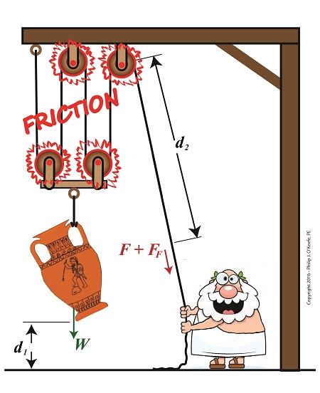
where, F is the entirely positive force, or work, exerted by human or machine to lift an object using a compound pulley. It represents an ideal but not real world scenario in which no friction is present within the pulley assembly.
The other force at play in our lifting scenario, FF, is less obvious to the casual observer. It’s the force, or work, which must be employed over and above the initial positive force to overcome the friction that’s always present between moving parts, in this case a rope moving through pulley wheels. The rope length extracted from the pulley to lift the object is d.
Now we’ll use this equation to understand why work input, WI, does not equal work output, WO, in a compound pulley arrangement where friction is present.
The first term in equation (1), (F × d), represents the work input as supplied by human or machine to lift the object. It is an idealistic scenario in which 100% of energy employed is directly conveyed to lifting. Stated another way, (F × d) is entirely converted into beneficial work effort, WO.
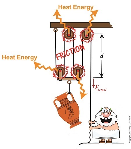
The second term, (FF × d), is the additional work input that’s needed to overcome frictional resistance present in the interaction between rope and pulley wheels. It represents lost work effort and makes no contribution to lifting the urn off the ground against the pull of gravity. It represents the heat energy that’s created by the movement of rope through the pulley wheels, heat which is entirely lost to the environment and contributes nothing to work output. Mathematically, this relationship between WO, WI, and friction is represented by,
WO = WI – (FF × d) (2)
In other words, work input is not equal to work output in a real world situation in which pulley wheels present a source of friction.
Next time we’ll run some numbers to demonstrate the inequality between WI and WO.
Copyright 2017 – Philip J. O’Keefe, PE
Engineering Expert Witness Blog
____________________________________ |
Tags: compound pulley, engineering, friction, heat energy, pulley, work input, work output
Posted in Engineering and Science, Expert Witness, Forensic Engineering, Innovation and Intellectual Property, Personal Injury, Product Liability | Comments Off on Work Input Does Not Equal Work Output
Saturday, January 7th, 2017
|
Last time we saw how the presence of friction reduces mechanical advantage in an engineering scenario utilizing a compound pulley. We also learned that the actual amount of effort, or force, required to lift an object is a combination of the portion of the force which is hampered by friction and an idealized scenario which is friction-free. Today we’ll begin our exploration into how friction results in reduced work input, manifested as heat energy lost to the environment. The net result is that work input does not equal work output and some of Mr. Toga’s labor is unproductive.
Friction Results in Heat and Lost Work Within a Compound Pulley
In a past blog, we showed how the actual force required to lift our urn is a combination of F, an ideal friction-free work effort by Mr. Toga, and FF , the extra force he must exert to overcome friction present in the wheels,
FActual = F + FF (1)
Mr. Toga is clearly working to lift his turn, and generally speaking his work effort, WI, is defined as the force he employs multiplied by the length, d, of rope that he pulls out of the compound pulley during lifting. Mathematically that is,
WI = FActual × d (2)
To see what happens when friction enters the picture, we’ll first substitute equation (1) into equation (2) to get WI in terms of F and FF,
WI = (F + FF ) × d (3)
Multiplying through by d, equation (3) becomes,
WI = (F × d )+ (FF × d) (4)
In equation (4) WI is divided into two terms. Next time we’ll see how one of these terms is beneficial to our lifting scenario, while the other is not.
Copyright 2017 – Philip J. O’Keefe, PE
Engineering Expert Witness Blog
____________________________________ |
Tags: compound pulley, engineering, friction, heat energy, lost work, mechanical advantage, pulley, reduced work, work input, work output
Posted in Engineering and Science, Expert Witness, Forensic Engineering, Innovation and Intellectual Property, Personal Injury, Product Liability, Professional Malpractice | Comments Off on Friction Results in Heat and Lost Work Within a Compound Pulley
Tuesday, December 13th, 2016
|
The presence of friction in mechanical designs is as guaranteed as conflict in a good movie, and engineers inevitably must deal with the conflicts friction produces within their mechanical designs. But unlike a good movie, where conflict presents a positive, engaging force, friction’s presence in pulleys results only in impediment, wasting energy and reducing mechanical advantage. We’ll investigate the math behind this phenomenon in today’s blog.
Friction Reduces Pulleys’ Mechanical Advantage
A few blogs back we performed a work input-output analysis of an idealized situation in which no friction is present in a compound pulley. The analysis yielded this equation for mechanical advantage,
MA = d2 ÷ d1 (1)
where d2 is the is the length of rope Mr. Toga extracts from the pulley in order to lift his urn a distance d1 above the ground. Engineers refer to this idealized frictionless scenario as an ideal mechanical advantage, IMA, so equation (1) becomes,
IMA = d2 ÷ d1 (2)
We also learned that in the idealized situation mechanical advantage is the ratio of the urn’s weight force, W, to the force exerted by Mr. Toga, F, as shown in the following equation. See our past blog for a refresher on how this ratio is developed.
IMA = W ÷ F (3)
In reality, friction exists between a pulley’s moving parts, namely, its wheels and the rope threaded through them. In fact, the more pulleys we add, the more friction increases.
The actual amount of lifting force required to lift an object is a combination of FF , the friction-filled force, and F, the idealized friction-free force. The result is FActual as shown here,
FActual = F + FF (4)
The real world scenario in which friction is present is known within the engineering profession as actual mechanical advantage, AMA, which is equal to,
AMA = W ÷ FActual (5)
To see how AMA is affected by friction force FF, let’s substitute equation (4) into equation (5),
AMA = W ÷ (F + FF) (6)
With the presence of FF in equation (6), W gets divided by the sum of F and FF . This results in a smaller number than IMA, which was computed in equation (3). In other words, friction reduces the actual mechanical advantage of the compound pulley.
Next time we’ll see how the presence of FF translates into lost work effort in the compound pulley, thus creating an inequality between the work input, WI and work output WO.
Copyright 2016 – Philip J. O’Keefe, PE
Engineering Expert Witness Blog
____________________________________ |
Tags: actual mechanical advantage, AMA, compound pulley, engineering, friction, friction force, ideal mechanical advantage, IMA, mechanical advantage, mechanical design, pulley, pulley friction, pulley work input, pulley work output, weight force
Posted in Engineering and Science, Expert Witness, Forensic Engineering, Innovation and Intellectual Property, Personal Injury, Product Liability | Comments Off on Friction Reduces Pulleys’ Mechanical Advantage
Wednesday, November 30th, 2016
|
We’ve been discussing the mechanical advantage that compound pulleys provide to humans during lifting operations and last time we hit upon the fact that there comes a point of diminished return, a reality that engineers must negotiate in their mechanical designs. Today we’ll discuss one of the undesirable tradeoffs that results in a diminished return within a compound pulley arrangement when we compute the length of rope the Grecian man we’ve been following must grapple in order to lift his urn. What we’ll discover is a situation of mechanical overkill – like using a steamroller to squash a bug.
Mechanical Overkill
Just how much rope does Mr. Toga need to extract from our working example compound pulley to lift his urn two feet above the ground? To find out we’ll need to revisit the fact that the compound pulley is a work input-output device.
As presented in a past blog, the equations for work input, WI, and work output, WO, we’ll be using are,
WI = F × d2
WO = W × d1
Now, ideally, in a compound pulley no friction exists in the wheels to impede the rope’s movement, and that will be our scenario today. Our next blog will deal with the more complex situation where friction is present. So for our example today, with no friction present, work input equals output…
WI = WO
… and this fact allows us to develop an equation in terms of the rope length/distance factors in our compound pulley assembly, represented by d1 and d2, …
F × d2 = W × d1
d2 ÷ d1 = W ÷ F
Now, from our last blog we know that W divided by F represents the mechanical advantage, MA, to Mr. Toga of using the compound pulley, which was found to be 16, equivalent to the sections of rope directly supporting the urn. We’ll set the distance factors up in relation to MA, and the equation becomes…
d2 ÷ d1 = MA
d2 = MA × d1
d2 = 16 × 2 feet = 32 feet
What we discover is that in order to raise the urn 2 feet, our Grecian friend must manipulate 32 feet of rope – which would only make sense if he were lifting something far heavier than a 40 pound urn.
In reality, WI does not equal WO, due to the inevitable presence of friction. Next time we’ll see how friction affects the mechanical advantage in our compound pulley.
Copyright 2016 – Philip J. O’Keefe, PE
Engineering Expert Witness Blog
____________________________________ |
Tags: compound pulley, engineer, force times distance, lift, mechanical advantage, mechanical design, pulley, rope length, work, work input, work output
Posted in Engineering and Science, Expert Witness, Forensic Engineering, Innovation and Intellectual Property, Personal Injury, Product Liability | Comments Off on Mechanical Overkill, an Undesirable Tradeoff in Compound Pulleys
Friday, November 18th, 2016
|
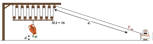
We’re all familiar with the phrase, “too much of a good thing.” As a professional engineer, I’ve often found this to be true. No matter the subject involved, there inevitably comes a point when undesirable tradeoffs occur. We’ll begin our look at this phenomenon in relation to compound pulleys today, and we’ll see how the pulley arrangement we’ve been working with encounters a rope length tradeoff. Today’s arrangement has a lot of pulleys lifting an urn a short distance.
We’ll be working with two distance/length factors and observe what happens when the number of pulleys is increased. Last time we saw how the compound pulley is essentially a work input-output device, which makes use of distance factors. In our example below, the first distance/length factor, d1, pertains to the distance the urn is lifted above the ground. The second factor, d2, pertains to the length of rope Mr. Toga extracts from the pulley while actively lifting. It’s obvious that some tradeoff has occurred just by looking at the two lengths of rope in the image below as compared to last week. What we’ll see down the road is that this also affects mechanical advantage.
The compound pulley here consists of 16 pulleys, therefore it provides a mechanical advantage, MA, of 16. For a refresher on how MA is determined, see our preceding blog.
Rope Length Tradeoff in a Compound Pulley
With an MA of 16 and the urn’s weight, W, at 40 pounds, we compute the force, F, Mr. Toga must exert to actively lift the urn higher must be greater than,
F > W ÷ MA
F > 40 Lbs. ÷ 16
F > 2.5 Lbs.
Although the force required to lift the urn is a small fraction of the urn’s weight, Mr. Toga must work with a long and unwieldy length of rope. How long? We’ll find out next time when we’ll take a closer look at the relationship between d1 and d2.
Copyright 2016 – Philip J. O’Keefe, PE
Engineering Expert Witness Blog
____________________________________ |
Tags: compound pulley, effor, force, mechanical advantage, professional engineer, pulley, rope length, weight force, work
Posted in Courtroom Visual Aids, Engineering and Science, Forensic Engineering, Innovation and Intellectual Property, Personal Injury, Product Liability, Professional Malpractice | Comments Off on Rope Length Tradeoff in a Compound Pulley
Sunday, November 6th, 2016
|
In our last blog we saw how adding extra pulleys resulted in mechanical advantage being doubled, which translates to a 50% decreased lifting effort over a previous scenario. Pulleys are engineering marvels that make our lives easier. Theoretically, the more pulleys you add to a compound pulley arrangement, the greater the mechanical advantage — up to a point. Eventually you’d encounter undesirable tradeoffs. We’ll examine those tradeoffs, but before we do we’ll need to revisit the engineering principle of work and see how it applies to compound pulleys as a work input-output device.
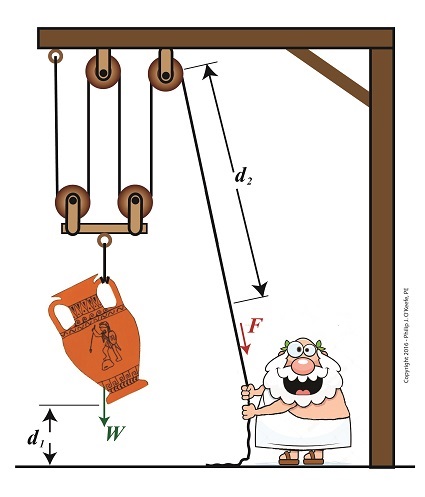
Pulleys as a Work Input-Outut Device
The compound pulley arrangement shown includes distance notations, d1 and d2. Their inclusion allows us to see it as a work input-output device. Work is input by Mr. Toga, we’ll call that WI, when he pulls his end of the rope using his bicep force, F. In response to his efforts, work is output by the compound pulley when the urn’s weight, W, is lifted off the ground against the pull of gravity. We’ll call that work output WO.
In a previous blog we defined work as a factor of force multiplied by distance. Using that notation, when Mr. Toga exerts a force F to pull the rope a distance d2 , his work input is expressed as,
WI = F × d2
When the compound pulley lifts the urn a distance d1 above the ground against gravity, its work output is expressed as,
WO = W × d1
Next time we’ll compare our pulley’s work input to output to develop a relationship between d1 and d2. This relationship will illustrate the first undesirable tradeoff of adding too many pulleys.
Copyright 2016 – Philip J. O’Keefe, PE
Engineering Expert Witness Blog
____________________________________ |
Tags: compound pulley, distance, engineering, engineering principle, force, mechanical advantage, pulley, weight, work, work input-output device, work of lifting
Posted in Engineering and Science, Expert Witness, Forensic Engineering, Innovation and Intellectual Property, Personal Injury, Product Liability | Comments Off on Pulleys as a Work Input-Outut Device
Thursday, October 27th, 2016
|
Last time we saw how compound pulleys within a dynamic lifting scenario result in increased mechanical advantage to the lifter, mechanical advantage being an engineering phenomenon that makes lifting weights easier. Today we’ll see how the mechanical advantage increases when more fixed and movable pulleys are added to the compound pulley arrangement we’ve been working with.
More Pulleys Increase Mechanical Advantage
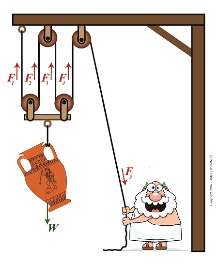
The image shows a more complex compound pulley than the one we previously worked with. To determine the mechanical advantage of this pulley, we need to determine the force, F5, Mr. Toga exerts to hold up the urn.
The urn is directly supported by four equally spaced rope sections with tension forces F1, F2, F3, and F4. The weight of the urn, W, is distributed equally along the rope, and each section bears one quarter of the load. Mathematically this is represented by,
F1 = F2 = F3 = F4 = W ÷ 4
If the urn’s weight wasn’t distributed equally, the bar directly above it would tilt. This tilting would continue until equilibrium was eventually established, at which point all rope sections would equally support the urn’s weight.
Because the urn’s weight is equally distributed along a single rope that’s threaded through the entire pulley arrangement, the rope rule, as I call it, applies. The rule posits that if we know the tension in one section of rope, we know the tension in all rope sections, including the one Mr. Toga is holding onto. Therefore,
F1 = F2 = F3 = F4 = F5 = W ÷ 4
Stated another way, the force, F5 , Mr. Toga must exert to keep the urn suspended is equal to the weight force supported by each section of rope, or one quarter the total weight of the urn, represented by,
F5 = W ÷ 4
If the urn weighs 40 pounds, Mr. Toga need only exert 10 pounds of bicep force to keep it suspended, and today’s compound pulley provides him with a mechanical advantage, MA, of,
MA = W ÷ F5
MA = W ÷ (W ÷ 4)
MA = 4
It’s clear that adding the two extra pulleys results in a greater benefit to the man doing the lifting, decreasing his former weight bearing load by 50%. If we added even more pulleys, we’d continue to increase his mechanical advantage, and he’d be able to lift far heavier loads with a minimal of effort. Is there any end to this mechanical advantage? No, but there are undesirable tradeoffs. We’ll see that next time.
Copyright 2016 – Philip J. O’Keefe, PE
Engineering Expert Witness Blog
____________________________________ |
Tags: compound pulley, engineering, fixed pulley, lifting, mechanical advantage, movable pulley, rope section, tension force
Posted in Engineering and Science, Forensic Engineering, Innovation and Intellectual Property, Personal Injury, Product Liability, Professional Malpractice | Comments Off on More Pulleys Increase Mechanical Advantage


