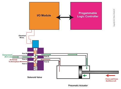
Last time we saw how a solenoid valve operates a pneumatic actuator in a jelly depositor in a food manufacturing plant. The operation was manual. In other words, an electrical switch had to be thrown by hand each time to get the solenoid to work. This can be rather tedious, when you consider the thousands of pastries that must be filled on each production run. Now, let’s see how the solenoid can be automatically turned on and off by an industrial control system.
In food manufacturing plants, industrial control systems are typically made up of programmable logic controllers, otherwise known as “PLCs.” The PLC is an industrial computer that is used to control equipment like conveyor belts, motors, pumps, robots, and solenoid valves. The PLC is connected to Input/Output Modules, or “I/O Modules.”
The I/O modules act as an interface between the computer and the equipment in the plant. As such, they contain a means to connect electrically to the computer and the plant equipment. In the case of our solenoid valve, the PLC computer program would turn the valve’s solenoid on and off. Whether it is turned on or off depends on the computer program’s timing and/or external sensors and how it feeds in conveyor belt/pastry position data to the PLC. The result is the automatic depositing of jelly filling as each pastry passes by the depositor nozzle.
The Depositor’s Industrial Control System
That wraps things up for our blog series on depositors. Next time we’ll move on to a new topic.
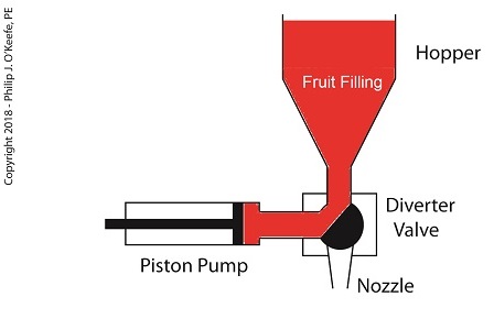
Our last blog introduced a project I oversaw while acting as a design engineer in a food manufacturing plant. The objective was to deposit fruit jelly into raw pastry dough as it whizzed along a production line conveyor belt before being sent off for baking. A special piece of equipment known as a depositor would be required to meet this challenge, and we’ll take a look at how one functions today. In fact, a jelly depositor acts very much as a human heart, as they’re both examples of positive displacement pumps.
A depositor is a device specifically made for the food industry. It consists of a hopper to hold the product to be deposited, in this case fruit jelly, which is discharged by the hopper into a rotating diverter valve and then on to a positive displacementpiston pump. See below.
A Jelly Depositor is a Positive Displacement Pump
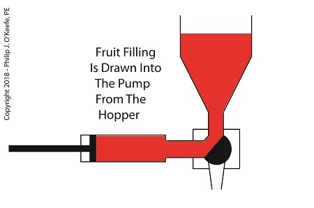
When the diverter valve rotates, a passageway opens to allow jelly to flow from the hopper into the piston pump. A pneumatic actuator, a device we’ll discuss in more depth next time, moves the pump’s piston to the left, away from the diverter valve, which allows the filling to be released into the pump from the hopper. At the end of the piston’s travel a set quantity of fruit jelly filling is drawn into the pump’s housing, just enough to fill one pastry. See below.
The Depositor Draws Filling Into The Pump
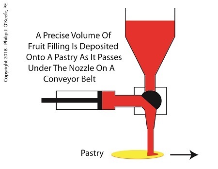
When the diverter valve rotates in the opposite direction, a passageway opens inside the valve that allows jelly filling to move from the pump to the nozzle. As the piston moves back toward the diverter valve the filling is forced out of the pump, through the nozzle, and into the pastry dough. The pump’s piston moves back and forth, that is, away from and then towards the transfer valve, ushering a set quantity of jelly filling through the mechanism each time. See below.
The Depositor Deposits The Filling
Now that we know how the depositor works, next time we’ll discuss the pneumatic actuator’s role in the filling process.
Last time we learned that the human heart functions as the greatest of all positive displacement pumps, moving a set quantity of blood through it at precise intervals during its operating cycle. Today we’ll begin our exploration into how positive displacement pumps are used in industry, specifically within a food manufacturing plant.
At one point in my career I was employed as a design engineer in a food manufacturing plant. The plant was owned by the leading manufacturer of bakery products in the United States, responsible for supplying restaurants, bakeries, and grocery stores with finished and partially finished pastry goods that they would then resell. The plant produced vast amounts of puff pastry dough products, all of which were formed and filled with various fillings while zipping along on a production line conveyor belt. One of the products was a fruit filled pastry in which the belt moved so quickly, depositing fruit fillings into the dough by hand would be impossible, resulting in a frenzied mess similar to what Lucy encountered when she worked in a candy factory.
Clearly, an automated machine would work better in this and other scenarios. We’ll see how one known as a depositor functions on a food pastry line next time.
Movies, that is 3D animations, are moving into the courtroom, and intended messages are made clearer than ever as a result. If a picture is worth a thousand words, how much more effective is a moving 3D image?
We’ve been viewing a static two-dimensional representation of a machine for the past two blogs. Have you been able to figure it out yet? Here it is again:
Would it help you to understand if I identified it as a piece of food manufacturing equipment equipped with a rake that aligns cookies on a conveyor belt? Would that verbal description allow you to “see” in your mind’s eye how it operates? Unless you had the right technical background, it’s unlikely.
Last week we introduced the verbiage person of ordinary skill in the art as a term widely used within patent litigation. This person is said to have the ability to interpret and understand patent drawings, and they typically possess a technical and/or scientific background.
But what if participants in a legal proceeding lack this background? Technical experts are often hired on as consultants to attorneys, and in some instances, judges, when clarification is required. These experts provide technical expertise and tutorials on the technology involved in complex cases, and it happens with regularity when the operation of a patented device is in question.
By employing 3D animations the expert can show how the device operates, rather than attempt to explain it using the technical language of their profession. The expert works closely with an animation artist to create the animation, providing the technical information that the animator will use to create the fully functional model. Animators do not typically have the technical background to accomplish this on their own and will require an ongoing dialog with the technical expert to create the animation.
And now the moment we’ve all been waiting for. Here is our static image brought to life through animation:
The animation commands the viewer’s attention and holds their interest, even if they have no background in engineering or science, and the device’s function is now made clear. It must be noted that in the patent drawing, part of the mechanism lies in front of a steel divider plate and part behind, but for purposes of clarity the entire mechanism has been shown to the front of the plate. Now there’s no doubt as to how the parts move together to even up the rows of cookies on the conveyor belt.
Next week we’ll talk about juries, perception, and the advantages of using courtroom animations when at trial.
___________________________________________
Last week our kitchen ceiling fan and light combo decided to stop working. We don’t like eating in the dark, so I was compelled to do some immediate troubleshooting. As an engineer with training in the workings of electricity I have a great respect for it. I’m well aware of potential hazards, and I took a necessary precaution before taking things apart and disconnecting wires. I made the long haul down the stairs to the basement, opened the circuit breaker in the electrical panel, and disabled the flow of electricity to the kitchen. My fears of potential electrocution having been eliminated, my only remaining fear was of tumbling off the ladder while servicing the fan.
Just as I took the precaution to disconnect the power supply before performing electrical maintenance in my home, workers in industrial settings must do the same, and a chief player in those scenarios is the motor overload relay discussed last week. It automatically shuts down electric motors when they become overheated. Let’s revisit that example now.
Figure 1
Our diagram in Figure 1 shows electric current flowing through the circuit by way of the red path. Even if this line were shut down, current would continue to flow along the path, because there is no means to disconnect the entire control system from the hot and neutral lines supplying power to it, that is, it is missing disconnect switches. Electric current will continue to pose a threat to workers were they to attempt a repair to the system. Now let’s see how we can eliminate potential hazards on the line.
Figure 2
In Figure 2 there is an obvious absence of the color red, indicating the lack of current within the system. We accomplished this with the addition of disconnect switches capable of isolating the motor control circuitry, thereby cutting off the hot and neutral lines of the electrical power supply and along with it the unencumbered flow of electricity.
These switches are basically the same as those seen in earlier diagrams in our series on industrial controls, the difference here is that the two switches are tied together by an insulated mechanical link. This link causes them to open and close at the same time. The switches are opened and closed manually via a handle. When the disconnect switches are both open electricity can’t flow and nothing can operate. Under these conditions there is no risk of a worker coming along and accidentally starting the conveyor motor.
To add yet another level of safety, disconnect switches are often tagged and locked once de-energized. This prevents workers from mistakenly closing them and starting the conveyor while maintenance is being performed. Brightly colored tags alert everyone that maintenance is taking place and the switches must not be closed. The lock that performs this safety function is actually a padlock. It’s inserted through a hole in the switch handle, making it impossible for anyone to flip the switch. Tags and locks are usually placed on switches by maintenance personnel before repairs begin and are removed when work is completed.
Now let’s see how our example control system looks in ladder diagram format.
Figure 3
Figure 3 shows a ladder diagram that includes disconnect switches, an emergency stop button, and the motor overload relay contacts. The insulated mechanical link between the two switches is represented by a dashed line. Oddly enough, engineering convention has it that the motor overload relay heater is typically not shown in a ladder diagram, therefore it is not represented here.
This wraps up our series on industrial control. Next time we’ll begin a discussion on mechanical clutches and how they’re used to transmit power from gasoline engines to tools like chainsaws and grass trimmers.
Last summer my wife and I did a lot of work in the garden. Many holes were dug, bags of garden soil lifted, and plants planted. It’s a new garden, and my wife has very big plans for it, so needless to say there was a lot of work to be done. On more than one occasion we would end the day moaning about our body aches and how we had overdone it. The next day we would hurt even worse, and we’d end up taking time off to recuperate. Pain is your body’s way of telling you that it needs attention, and you’d better listen to it or you may have an even heavier price to pay down the road.
Electric motors can get overworked, just like our bodies. Motors are often placed into situations where they are expected to perform tasks beyond their capability. Sometimes this happens through poor planning, sometimes due to wishful thinking on the user’s part. Motors can sustain damage when stressed in this way, but they don’t have a pain system to tell them to stop. Instead, motors benefit by a specific type of electric relay known as an overload relay. But before we get into how an overload relay works, let’s get a better understanding of how overloads happen.
Suppose we’re back in the telephone factory discussed in previous blogs, watching a conveyor belt move phones through the manufacturing process. An electric motor drives the conveyor belt by converting electrical energy into mechanical energy. Everything is moving along normally when all of a sudden a machine malfunctions. Telephones start piling up on a belt, and the pile up gets so bad the belt eventually gets jammed and its motor overloaded. If the electricity flow to the motor isn’t shut down promptly by means of a nearby emergency stop button or an astute operator sitting in central control, then an even bigger problem is in the making, that of a potential fire.
When electricity is applied to motors they begin to operate, and their natural tendency is to want to keep operating. They do so by continuously drawing energy from the electric current being supplied to them. The greater the workload demand on the motor, the more current it requires to operate.
When motors become overloaded as in the scenario presented above, they continue to draw energy unless forced to a stop. The result is an overabundance of current flowing through the motor and no outlet for its task of converting electrical energy into mechanical energy. And where is all that pent up energy to go? It becomes heat energy trapped inside the motor itself, and this heat can build up to the point where the motor becomes damaged or even bursts into flames.
Next time we’ll look at how overload relays work to keep electric motors from overheating, just as our body’s pain sensors protect us from overdoing it.
Electric motors are everywhere, from driving the conveyor belts, tools, and machines found in factories, to putting our household appliances in motion. The first electric motors appeared in the 1820s. They were little more than lab experiments and curiosities then, as their useful potential had not yet been discovered. The first commercially successful electric motors didn’t appear until the early 1870s, and they could be found driving industrial devices such as pumps, blowers, and conveyor belts.
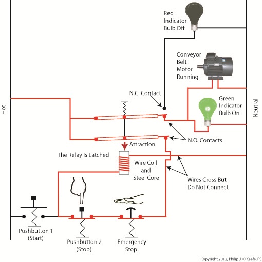
In our last blog we learned how a latched electric relay was unlatched at the push of a button, using red and green light bulbs to illustrate the control circuit. Now let’s see in Figure 1 how that circuit can be modified to include the control of an electric motor that drives, say, a conveyor belt inside a factory.
Figure 1
Again, red lines in the diagram indicate parts of the circuit where electrical current is flowing. The relay is in its normal state, as discussed in a previous article, so the N.O. contacts are open and the N.C. contact is closed. No electric current can flow through the conveyor motor in this state, so it isn’t operating. Our green indicator bulb also does not operate because it is part of this circuit. However current does flow through the red indicator bulb via the closed N.C. contact, causing the red bulb to light.
The red and green bulbs are particularly useful as indicators of the action taking place in the electric relay circuit. They’re located in the conveyor control panel along with Buttons 1 and 2, and together they keep the conveyor belt operator informed as to what’s taking place on the line, such as, is the belt running or stopped? When the red bulb is lit the operator can tell at a glance that the conveyor is stopped. When the green bulb is lit the conveyor is running.
So why not just take a look at the belt itself to see what’s happening? Sometimes that just isn’t possible. Control panels are often located in central control rooms within large factories, which makes it more efficient for operators to monitor and control all operating equipment from one place. When this is the case, the bulbs act as beacons of the activity taking place on the line. Now, let’s go to Figure 2 to see what happens when Button 1 is pushed.
Figure 2
The relay’s wire coil becomes energized, causing the relay armatures to move. The N.C. contact opens and the N.O. contacts close, making the red indicator bulb go dark, the green indicator bulb to light, and the conveyor belt motor to start. With these conditions in place the conveyor belt starts up.
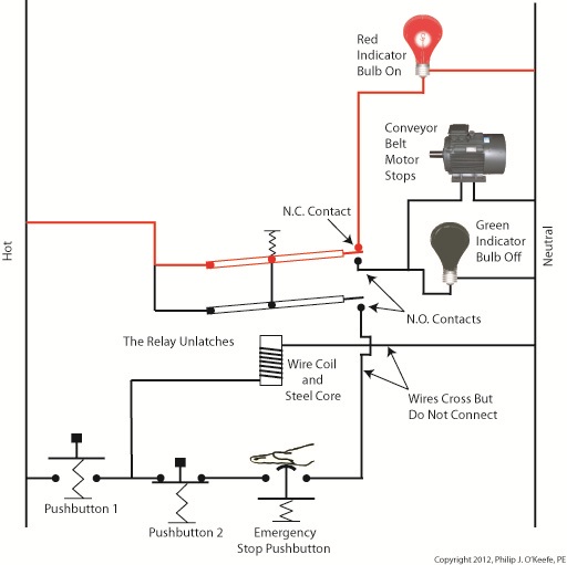
Now, let’s look at Figure 3 to see what happens when we release Button 1.
Figure 3
With Button 1 released the relay is said to be “latched” because current will continue to flow through the wire coil via one of the closed N.O. contacts. In this condition the red bulb remains unlit, the green bulb lit, and the conveyor motor continues to run without further human interaction. Now, let’s go to Figure 4 to see how we can stop the motor.
Figure 4
When Button 2 is depressed current flow through the relay coil interrupted. The relay is said to be unlatched and it returns to its normal state where both N.O. contacts are open. With these conditions in place the conveyor motor stops, and the green indicator bulb goes dark, while the N.C. contact closes and the red indicator bulb lights. Since the relay is unlatched and current no longer flows through its wire coil, the motor remains stopped even after releasing Button 2. At this point we have a return to the conditions first presented in Figure 1. The ladder diagram shown in Figure 5 represents this circuit.
Figure 5
Next time we’ll introduce safety elements to our circuit by introducing emergency buttons and motor overload switches.
You’ve probably heard the saying, “asleep at the switch.” It’s usually associated with some sort of disaster, found later to have been caused by human error. Someone wasn’t paying attention, and something very bad happened. The meltdown of the Soviet nuclear power plant Chernobyl in 1986 comes to mind. You may be surprised to learn that the saying has its origins in the world of industrial controls, or more specifically, manual controls, as we’ll see in this article.
Last week when we opened our discussion on manual controls, we talked about how they work just as their name implies, that is, someone must manually press a button or throw a switch in order to initiate a factory operation. In other words, a manual control requires human intervention to initiate an action, such as pushing the start button. The machine will then continue to run until a person hits the stop button.
Let’s go now on a virtual field trip into a telephone factory to see how a basic manual control system works. It has a conveyor belt operated by an electric motor, and this motor is connected by wires and a power switch to a 120 volt power source of alternating current. Figure 1 illustrates what we mean. It shows that when the power switch is in the open position, a physical air gap exists within the electrical circuit. This prevents electricity from flowing through the wire because electricity can’t jump over gaps.
Figure 1 – Open Power Switch
Enter a human into the scenario, someone who grabs the power switch handle and manually closes it, eliminating the air gap. See Figure 2.
Figure 2 – Closed Power Switch
When the power switch is closed, a metal conductor bridges the gap, causing electricity to flow through the metal conductor to the electric motor in the circuit. This brings life to the conveyor belt. As long as the power switch remains closed, the conveyor belt will continue to operate.
That’s it, that’s a basic manual control system. It’s simple to operate, but it does have one major flaw. It requires constant monitoring by a human. Aside from opening and closing a power switch, humans are required to monitor operations, in case something goes wrong. The operator watching over an industrial machine performs the same function as the pilot on a plane, that is, to start-stop operations, and to intervene in case of an emergency. Computers fly modern jets. Pilots serve as trouble shooters when the unanticipated disaster situation occurs, because computers can’t yet creatively problem solve.
Next time we’ll introduce the element of an automatic control system, which will virtually eliminate the need for human intervention and with it human error.
When I was a child in school I loved field trips. They didn’t happen too often, but when they did they were a welcomed break from the routine of the classroom. Once we went on a tour of a large factory that made telephones. During the tour we walked amongst gargantuan machines, conveyor belts, furnaces, boilers, pumps, and compressors, all energized and working together to transform raw materials into telephones. Sequences of manufacturing and assembly operations, from the simple to the most complex, were carefully orchestrated with no apparent human intervention.
The equipment in the telephone factory was certainly impressive to watch, and our tour guides did a fine job of explaining what was happening, except for one important detail. I realized after we left that no one had explained who or what was actually controlling the machinery. I realized even then that machines can’t think for themselves. They can only do what humans tell them to do.
I didn’t know it at the time, but the telephone factory setup included some interesting examples of industrial control systems. Industrial control systems can be broken down into two basic categories, manual controls and automatic controls. Manual controls work as their name implies, that is, someone must manually press a button or throw a switch to initiate factory operations. This involves continual monitoring of processes, coupled with hands-on activities to keep everything working.
Automatic controls still require human intervention to some extent, such as initiating operations, but once that’s done they move into self-regulation mode until the operations are shut down at the end of production. Employees are thus freed up to spend time doing things which are not automated. Automatic controls are excellent at handling mundane, repetitive tasks that humans tend to get quickly bored with. Boredom leads to a lack of attention, and this may lead to accidents, so utilizing automatic controls often makes for a safer work environment.
Next time we’ll begin our examination of how manual and automatic controls work within the context of an industrial setting. To begin, we’re going to take a virtual field trip back to the telephone factory and look at some basic industrial control examples.
Imagine a doctor not washing his hands in between baby deliveries. Unbelievable but true, this was a widespread practice up until last century when infections, followed by death of newborns, was an all-too common occurrence in hospitals across the United States. It took an observant nurse to put two and two together after watching many physicians go from delivery room to delivery room, mother to mother, without washing their hands. Once hand washing in between deliveries was made mandatory, the incidence of infection and death in newborns plummeted.
Why wasn’t this simple and common sense solution instituted earlier? Was it ignorance, negligence, laziness, or a combination thereof that kept doctors from washing up? Whatever the root cause of this ridiculous oversight, it remains a fact of history. Common sense was finally employed, and babies’ lives saved.
The same common sense is at play in the development of the FDA’s Hazard Analysis Critical Control Point (HACCP) policy, which was developed to ensure the safe production of commercial food products. Like the observant nurse who played watchdog to doctors’ poor hygiene practices and became the catalyst for improved hospital procedures set in place and remaining until today, HACCP policy results in a proactive strategy where hazards are identified, assessed, and then control measures developed to prevent, reduce, and eliminate potential hazards.
In this article, we’ll begin to explore how engineers design food processing equipment and production lines in accordance with the seven HACCP principles. You will note that here, once again, the execution of common sense can solve many problems.
Principle 1: Conduct a hazard analysis. – Those involved in designing food processing equipment and production lines must proactively analyze designs to identify potential food safety hazards. If the hazard analysis reveals contaminants are likely to find their way into food products, then preventive measures are put in place in the form of design revisions.
For example, suppose a food processing machine is designed and hazard analysis reveals that food can accumulate in areas where cleaning is difficult or impossible. This accumulation will rot with time, and the bacteria-laden glop can fall onto uncontaminated food passing through production lines.
As another example, a piece of metal tooling may have been designed with the intent to form food products into a certain shape, but hazard analysis reveals that the tooling is too fragile and cannot withstand the repeated forces imposed on it by the mass production process. There is a strong likelihood that small metal parts can break off and enter the food on the line.
Next time we’ll move on to HACCP Principle 2 and see how design engineers control problems identified during the hazard analysis performed pursuant to Principle 1.


