|
During 6th grade science we had a chapter on Simple Machines, and my textbook listed a common lever as an example, the sort that can be used to make work easier. Its illustration showed a stick perched atop a triangular shaped stone, appearing very much like a teeter-totter in the playground. A man was pushing down on one end of the stick to move a large boulder with the other end. Staring at it I thought to myself, “That doesn’t look like a machine to me. Where are its gears?” That day I learned about more than just levers, I learned to expect the unexpected when it comes to machines.
Last time we learned that under patent law the machine referred to in federal statute 35 USC § 101 includes any physical device consisting of two or more parts which dynamically interact with each other. We looked at how a purely mechanical machine, such as a diesel engine, has moving parts that are mechanically linked to dynamically interact when the engine runs. Now, lets move on to less obvious examples of what constitutes a machine. Would you expect a modern electronic memory stick to be a machine? Probably not. But, under patent law it is. It’s an electronic device, and as such it’s made up of multiple parts, including integrated circuit chips, resistors, diodes, and capacitors, all of which are soldered to a printed circuit board where they interact with one another. They do so electrically, through changing current flow, rather than through physical movement of parts as in our diesel engine. A transformer is an example of another type of machine. An electrical machine. Its fixed parts, including wire coils and steel cores, interact dynamically both electrically and magnetically in order to change voltage and current flow. Electromechanical, the most complex of all machine types, includes the kitchen appliances in your home. They consist of both fixed and moving parts, along with all the dynamic interactions of mechanical, electronic, and electrical machines. Next time we’ll continue our discussion on the second hurtle presented by 35 USC § 101, where we’ll discuss what is meant by article of manufacture. ___________________________________________ |
Posts Tagged ‘current flow’
Determining Patent Eligibility – Part 4, Machines of a Different Kind
Sunday, April 28th, 2013
Transistors – Voltage Regulation Part XVI
Monday, November 5th, 2012
Transistors – Voltage Regulation Part XII
Sunday, October 7th, 2012|
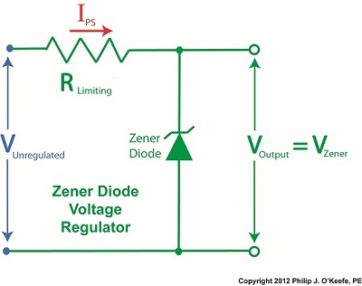
Let’s continue our discussion with regard to the example circuit discussed last time and see how the Zener diode works in tandem with the limiting resistor to control current flow and hold the output voltage at a constant level.
Figure 1
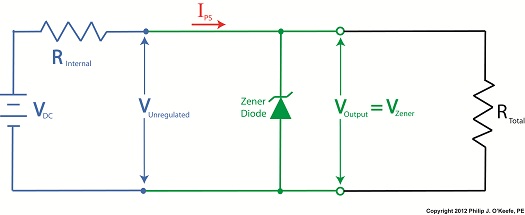
To recap our discussion from last week, the unregulated power supply portion of the circuit in Figure 1 generates an unregulated voltage, VUnregulated. Then the Zener diode, which acts as a voltage regulator, takes in VUnregulated and converts it into a steady output voltage, VOutput. Because these output terminals are connected to the ends of the Zener diode, VOutput is equal to the voltage put out by it, denoted as VZener. The Zener diode, an excellent negotiator of current, is essentially involved in a constant trade off, substituting electric current that originates in the unregulated power supply portion of the circuit for voltage, VOutput, that will serve to power the external supply circuit. In other words, the Zener diode draws as much current, IZ, through it as it needs, its objective being to keep VOutput at a constant level, and it will continue to provide this constant output, despite the fact that VUnregulated varies considerably. So, where does the current IZ come from? From IPS, that is, the current flowing from the unregulated power supply area, as shown in Figure 1. IPS flows through the limiting resistor to a junction within the circuit. At this junction, IZ splits off from IPS and continues on to the Zener diode, while current I splits off from IPS on its way to the total internal resistance, RTotal, in the external supply circuit. What this means is that when you add IZ and I together, you get IPS. Mathematically speaking this is represented as: IPS = IZ + I Why solve for IPS? We’ll see why this is important when we revisit Ohm’s Law next week and gain a fuller understanding of how IPS, VUnregulated, VZener, and RLimiting relate to each other with regard to the Zener diode. ____________________________________________ |

Transistors – Voltage Regulation Part X
Monday, September 24th, 2012| Through the ages it’s been common practice to name important discoveries after those who discovered them. For example, James Watt was a mechanical engineer who improved the steam engine by finding a solution to the problem of steam condensing into water inside the engine, a phenomenon which resulted in the engine cooling and reducing its efficiency. Thus it was fitting that a metric unit of power, the watt, was named in his honor. Today we’ll become acquainted with the man behind the naming of the Zener diode, Clarence Zener, and take a look at his contributions with regard to the function of this electrical component.
Last time we began our discussion on electrical components known as diodes and saw how they’re used on circuit paths to govern the flow of current. The Zener diode is a particular type of diode and a key component in transistorized voltage regulator circuits, as we’ll see later. For now, let’s see how it works. The symbol for the Zener diode is almost identical to that of a standard diode, introduced in my previous blog, but the Zener version has a bent line going through it resembling a distorted letter “z.” See Figure 1.
Figure 1
Electric current flows through the Zener Diode just as it does through a standard diode. But when the current flows in reverse, that’s where the similarity ends. See Figure 2. Figure 2
When current tries to flow in the reverse direction, the Zener diode acts as an electrical conductor and allows current to pass through it. In other words, it doesn’t block current flow as standard diodes do. At this point, you may be asking, “What’s so special about that?” Perhaps you’ve made the connection that it behaves no differently than a metal wire. But that isn’t entirely correct. You see, when current passes in the reverse direction through the Zener diode, it maintains a constant voltage. This is called the Zener Voltage and is denoted as VZener. The significance here is that within the circuit, any electronic component connected across the leads of a Zener diode will be supplied with a constant, unchanging voltage. Thus the Zener diode works as a voltage regulator, enabling devices connected to it to have smooth, uninterrupted operation at a constant voltage. It should be noted that this phenomenon only happens when the current flowing through the Zener diode is flowing in reverse. Next time we’ll look at a basic regulated power supply circuit to see how a Zener diode is incorporated in order to maintain a consistent output voltage. ____________________________________________ |


Transistors – Voltage Regulation Part IX
Sunday, September 16th, 2012| One way streets frustrate me, and I usually end up wasting a lot of time and gas driving in circles to get to my destination. Generally speaking, I prefer a two way street. Electric current flowing through electronic circuits is somewhat analogous to traffic flow. There are circuit paths that act like one way streets and others that act like two-way.
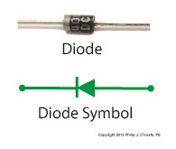
An electrical component called a diode can be used on circuit paths to govern the flow of current. They are a key component in basic transistorized voltage regulator circuits, as we’ll see later. For now, let’s get a basic understanding of how they work. Diodes are typically made of a semiconductor material, such as the element germanium. These materials behave in a complex way that fall along the lines of quantum physics. Esoteric phrases such as electron-hole theory, crystalline atomic lattice theory, and impurity doping are some of the concepts involved and would require a book onto themselves to explain. For the purposes of this article all we have to know is that semiconductors have two properties. The first property is that of an electrical conductor, that is, a material which allows electric current to pass through it. Copper wire is a good example of this. The second property is that of an electrical insulator, which blocks the flow of electric current. Materials such as glass, wood, and rubber fall into the insulator category. A photo of a diode is shown in Figure 1, along with its symbol used in electrical schematics.
Figure 1
When electric current flows through a diode in one direction, as shown in Figure 2, the semiconductor material inside of it acts as a conductor, ushering it along a single path.
Figure 2
When current tries to flow through the diode in the reverse direction, the semiconductor material acts as an insulator. That is, it blocks the flow of current as shown in Figure 3.
Figure 3
So we see that diodes can act like one way streets, restricting current flow. But, not all diodes work this way. Next week we’ll introduce a special kind of diode called the Zener diode, which allows current to flow in two different directions, and we’ll see how this functionality is put to work in regulated power supplies. ____________________________________________ |


Transistors – Voltage Regulation Part VI
Sunday, August 26th, 2012| Believe it or not as a kid in grade school I used to hate math, particularly algebra. None of my teachers were able to decipher its complexities and render it comprehensible to me or the majority of my classmates. Then in high school everything changed. I had Mr. Coleman for freshman algebra, and he had a way of making it both understandable and fun, in a challenging kind of way. With 40 years of teaching under his belt, Mr. Coleman knew exactly how to convey the required information in an understandable manner, and to this day I find his insights useful in solving engineering calculations.
Last time we began our discussion on Ohm’s Law and how it may be applied to our example circuit to solve for the electrical current flowing through it. Let’s continue our discussion to see how the Law applies to only one part of the circuit. Then, we’ll use a little algebra to show how the output voltage of an unregulated power supply is affected by changes in RTotal.
Figure 1
To help us see things more clearly, in Figure 1 we’ll cover up the inside workings of the unregulated power supply side of the circuit and concentrate on the external supply part of the circuit alone. Since RTotal is connected to the terminals of the power supply, the voltage applied to RTotal is the same as the power supply output voltage, VOutput. In my previous article, we learned that according to Ohm’s Law, the current flowing through a resistance is equal to the voltage applied to it, divided by the resistance. The fact that RTotal is connected to the two output terminals like we see in Figure 1, allows us to use Ohm’s law to solve for the electrical current, I, flowing through RTotal: I = VOutput ÷ RTotal Now let’s pull the cover off of the unregulated power supply again to see what’s going on within the circuit as a whole.
Figure 2
In Figure 2 we can see that the current, I, flowing through RTotal is the same current flowing through the balance of the circuit. In the preceding blog we found that value to be: I = VDC ÷ (RInternal + RTotal) We can combine the above two equations for I to develop an algebraic relationship between VOutput and RInternal, RTotal, and VDC: VOutput ÷ RTotal = VDC ÷ (RInternal + RTotal) Then, by rearranging terms and applying the cross multiplication principle of algebra we can solve for VOutput. This involves multiplying both sides of the equation by RTotal: VOutput = RTotal × (VDC ÷ (RInternal +RTotal)) This equation tells us that although RInternal doesn’t fluctuate, VOutput will fluctuate when RTotal does. This fact is demonstrated in our equation when we make use of algebra. That is to say, when a term changes on one side of the equation, it causes the other side of the equation to change as well. In this case, when RTotal changes, it causes VOutput to change in proportion to the fixed values of VDC and RInternal. Next time we’ll look at another shortcoming of unregulated power supplies, more specifically, how one supply can’t power multiple electrical circuits comprised of different voltages. ____________________________________________ |


Transistors – Voltage Regulation Part III
Tuesday, August 7th, 2012| When my daughter was seven she found out about Ohm’s Law the hard way, although she didn’t know it. She had accidentally bumped into her electric toy train, causing its metal wheels to derail and fall askew of the metal track. This created a short circuit, causing current to flow in an undesirable direction, that is, through the derailed wheels rather than along the track to the electric motor in the locomotive as it should.
What happened during the short circuit is that the bulk of the current began to follow through the path of least resistance, that of the derailed wheels, rather than the higher resistance of the electric motor. Electric current, always opportunistic, will flow along its easiest course, in this case the short, thick metal of the wheels, rather than work its way along the many feet of thin metal wire of the motor’s electromagnetic coils. With its wheels sparking at the site of derailment the train had become an electric toaster within seconds, and the carpet beneath the track began to burn. Needless to say, mom wasn’t very happy. In this instance Ohm’s Law was at work, with a decidedly negative outcome. The Law’s basic formula concerning the toy train would be written as: I = V ÷ Rwhere, I is the current flowing through the metal track, V is the track voltage, and R is the internal resistance of the metal track and locomotive motor, or in the case of a derailment, the metal track and the derailed wheel. So, according to the formula, for a given voltage V, when the R got really small due to the derailment, I got really big. But enough about toy trains. Let’s see how Ohm’s Law applies to an unregulated power supply circuit. We’ll start with a schematic of the power supply in isolation.
Figure 1The unregulated power supply shown in Figure 1 has two basic aspects to its operation, contained within a blue dashed line. The dashed line is for the sake of clarity when we connect the power supply up to an external circuit which powers peripheral devices later on. The first aspect of the power supply is a direct current (DC) voltage source, which we’ll call VDC. It’s represented by a series of parallel lines of alternating lengths, a common representation within electrical engineering. And like all electrical components, the power supply has an internal resistance, such as discussed previously. This resistance, notated RInternal, is the second aspect of the power supply, represented by another standard symbol, that of a zigzag line. Finally, the unregulated power supply has two output terminals. These will connect to an external supply circuit through which power will be provided to peripheral devices. Next time we’ll connect to this external circuit, which for our purposes will consist of an electric relay, buzzer, and light to see how it all works in accordance with Ohm’s Law. ____________________________________________ |

Transistors – Voltage Regulation Part II
Sunday, July 29th, 2012| I joined the Boy Scouts of America as a high schooler, mainly so I could participate in their Explorer Scout program and learn about electronics. I will forever be grateful to the Western Electric engineers who volunteered their personal time to stay after work and help me and my fellow Scouts build electronic projects. The neatest part of the whole experience was when I built my first regulated power supply with their assistance inside their lab. But in order to appreciate the beauty of a regulated power supply we must first understand the shortcomings of an unregulated one, which we’ll begin to do here.
Last time we began to discuss how the output voltage of an unregulated power supply can vary in response to power demand, just as when sprinklers don’t have sufficient water flow to cover a section of lawn. Let’s explore this concept further.
Figure 1
Figure 1 shows a very basic representation of a microprocessor control system that operates three components, an electric relay (shown in the blue box), buzzer, and light. These three components have a certain degree of internal electrical resistance, annotated as RR, RB, and RL respectively. This is because they are made of materials with inherent imperfections which tend to resist the flow of electric current. Imperfections such as these are unavoidable in any electronic device made by humans, due to impurities within metals and irregularities in molecular structure. When the three components are activated by the microprocessor chip via field effect transistors, denoted as FET 1, 2 and 3 in the diagram, their resistances are connected to the supply circuit. In other words, RR, RB, and RL create a combined level of resistance in the supply circuit by their connectivity to it. If a single component were to be removed from the circuit, its internal resistance would also be removed, resulting in a commensurate decrease in total resistance. The greater the total resistance, the more restriction there is to current flow, denoted as I. The greater the resistance, the more I is caused to decrease. In contrast, if there is less total resistance, I increases. The result of changing current flow resistance is that it causes the unregulated power supply output voltage to change. This is all due to an interesting phenomenon known as Ohm’s Law, represented as this within engineering circles: V = I × R where, V is the voltage supplied to a circuit, I is the electrical current flowing through the circuit, and R is the total electrical resistance of the circuit. So, according to Ohm’s Law, when I and R change, then V changes. Next time we’ll apply Ohm’s Law to a simplified unregulated power supply circuit schematic. In so doing we’ll discover the mathematical explanation to the change in current flow and accompanying change in power supply output voltage we’ve been discussing. ____________________________________________ |

Transistors – Digital Control Interface, Part I
Monday, June 18th, 2012| In the navy, the captain is the brains behind a ship’s operations. He gathers information, makes important decisions, then issues orders. He’s not there to roll up his sleeves and swab the decks. The captain relies on the ship’s officers to act as an interface between himself and the sailors that perform the physical labor required on deck.
In this article we’ll see how the FET, that is, the field effect transistor, performs much the same role as the ship’s officers when it is used within electronic controls. There it acts as an interface between electronic components that issue commands and the electrical devices that carry them out. Last week we became familiar with field effect transistors and how their control of electrical current flow is analogous to how a faucet controls the flow of water. Although FETs can be used to vary the flow of current, they’re usually employed to perform a much simpler task, that of simply turning flow on or off, with no in-between modality. Like the captain of a ship, microprocessor and logic chips are the brains behind the operation in all sorts of industrial and consumer electronics. Figure 1 shows a few of them. Figure 1
The chips, which operate on low voltage, contain entire computer programs within them that gather information, make decisions, then instruct the higher voltage devices like motors, electrical relays, light bulbs, and audible alarms to follow. By “information,” I mean data signals received by the chip from its input connections to sensors, buttons, and other electrical components. This data informs the chip’s computer program of important operational information, like whether buttons have been pressed, switches are activated, and temperatures are normal. Based on this data, “decisions” are made by the chip using the logic contained within its program, then, depending on the decisions made, “commands” are issued by the chip. The commands, in the form of electrical output signals, are put into action by the work horses, the higher voltage devices. They, like a ship’s sailors, perform the actual physical work. There is one problem presented by this scenario, however. The electric output signals from the lower voltage chips are not suited to directly control the higher voltage devices because the signal voltage put out by the chips is too low. Even if the chip was designed to work at a higher voltage, the high level of current drawn by the motors, relays, and bulbs would lead to damage of the delicate circuitry within the chip. The chips must therefore rely on the FET to act as a digital control interface between them and the higher voltage devices, much as the ship’s captain depends on his subordinates to carry out his orders. Next week we’ll look at a real life example of how a digital interface is put into operation within an industrial product.
____________________________________________ |

Transistors
Sunday, June 10th, 2012| Back in the 60s my dad spent about $25 to buy a small transistor radio. That was a lot of money in those days, but well worth it. The new transistor technology allowed for a much less cumbersome radio to be produced. No more lugging around big radios armed with heavy vacuum tubes. In the years that followed the word transistor became a household word. They were employed in a variety of ways within televisions and other electronic devices, increasing both their reliability and functionality.
So what is a transistor and what does it do? It’s an electronic component, developed in the late 1940s. The first transistor was about as big as a softball and crudely made. As such, it was too impractical for commercial use. Then in the l950s technological advancements made commercial production of smaller, high-quality transistors possible. Transistors enjoyed widespread introduction to the consuming mainstream in the l960s, and since then they’ve been made in many different types, shapes, and sizes. Some are shown in Figure 1 below. Figure 1
A commonly used type of transistor is called a field effect transistor, or FET, one of which is shown in Figure 2. The FET has three metal leads which allow it to be connected into electrical circuits. These leads are referred to as the drain (D), the source (S), and the gate (G).
Figure 2
FET’s control the flow of current within an electronic circuit. A good way to understand what they do is to consider the analogy of water flowing through a faucet.
Figure 3
Figure 3 shows a faucet, complete with valve and handle. With the valve closed the flow of water is completely shut off. If the valve is opened partway by rotation of the handle, a trickle of water emerges. The more the handle is turned and valve is opened, the greater the flow of water. The FET shown in Figure 4 operates a lot like a faucet, but with regard to electrical current. Figure 4
The FET controls the flow of current flowing through its D and S leads, but it does not employ a valve or handle to do it. Rather, flow rate is controlled by application of a small amount of voltage to the G lead. The voltage’s influence on the G lead influences the FET to permit current to flow in through the D lead, then out through the S lead. The amount of voltage applied to the G lead is directly related to how much current will be allowed to flow. In this example the D lead on the FET is connected to a 10 volt direct current (VDC) power supply. The S lead is connected to a flashlight bulb which is connected to electrical ground. If you will remember from previous blogs, electric current naturally wants to flow from the supply source to ground, much like water wants to naturally flow downhill. If the bulb was connected directly to the 10 VDC power supply, current would flow through unimpeded and the bulb would light. However, in Figure 4 the FET acts as a regulating device. It’s connected between the 10 VDC power supply and the bulb. When no voltage is applied to the G lead the FET acts like a closed valve and current is unable to flow. Without current we, of course, have no light. When a low amount of voltage, say one volt, is applied to the G lead, the FET acts like a partially opened valve. It permits a trickle of current to flow from the 10 VDC supply to the bulb, and the bulb glows dimly. As voltage to G increases the FET valve opens further, permitting more current to flow. The bulb glows with increasing brightness. When the voltage applied to G increases to the point the FET valve is opened fully, in our example that is 2 volts, full current is allowed to flow from the 10 VDC supply to the bulb. The bulb glows brightly. Generally speaking, the voltage required to be applied to G for control of current flow through an FET depends on overall design and the particular application within an electrical circuit. FETs are often used within electronic devices to turn things on and off, with no other function in between. Next time we’ll look at some example circuits to see how it’s done. ____________________________________________ |


