|
During 6th grade science we had a chapter on Simple Machines, and my textbook listed a common lever as an example, the sort that can be used to make work easier. Its illustration showed a stick perched atop a triangular shaped stone, appearing very much like a teeter-totter in the playground. A man was pushing down on one end of the stick to move a large boulder with the other end. Staring at it I thought to myself, “That doesn’t look like a machine to me. Where are its gears?” That day I learned about more than just levers, I learned to expect the unexpected when it comes to machines.
Last time we learned that under patent law the machine referred to in federal statute 35 USC § 101 includes any physical device consisting of two or more parts which dynamically interact with each other. We looked at how a purely mechanical machine, such as a diesel engine, has moving parts that are mechanically linked to dynamically interact when the engine runs. Now, lets move on to less obvious examples of what constitutes a machine. Would you expect a modern electronic memory stick to be a machine? Probably not. But, under patent law it is. It’s an electronic device, and as such it’s made up of multiple parts, including integrated circuit chips, resistors, diodes, and capacitors, all of which are soldered to a printed circuit board where they interact with one another. They do so electrically, through changing current flow, rather than through physical movement of parts as in our diesel engine. A transformer is an example of another type of machine. An electrical machine. Its fixed parts, including wire coils and steel cores, interact dynamically both electrically and magnetically in order to change voltage and current flow. Electromechanical, the most complex of all machine types, includes the kitchen appliances in your home. They consist of both fixed and moving parts, along with all the dynamic interactions of mechanical, electronic, and electrical machines. Next time we’ll continue our discussion on the second hurtle presented by 35 USC § 101, where we’ll discuss what is meant by article of manufacture. ___________________________________________ |
Posts Tagged ‘diode’
Determining Patent Eligibility – Part 4, Machines of a Different Kind
Sunday, April 28th, 2013
Transistors – Voltage Regulation Part XII
Sunday, October 7th, 2012|
Let’s continue our discussion with regard to the example circuit discussed last time and see how the Zener diode works in tandem with the limiting resistor to control current flow and hold the output voltage at a constant level.
Figure 1
To recap our discussion from last week, the unregulated power supply portion of the circuit in Figure 1 generates an unregulated voltage, VUnregulated. Then the Zener diode, which acts as a voltage regulator, takes in VUnregulated and converts it into a steady output voltage, VOutput. Because these output terminals are connected to the ends of the Zener diode, VOutput is equal to the voltage put out by it, denoted as VZener. The Zener diode, an excellent negotiator of current, is essentially involved in a constant trade off, substituting electric current that originates in the unregulated power supply portion of the circuit for voltage, VOutput, that will serve to power the external supply circuit. In other words, the Zener diode draws as much current, IZ, through it as it needs, its objective being to keep VOutput at a constant level, and it will continue to provide this constant output, despite the fact that VUnregulated varies considerably. So, where does the current IZ come from? From IPS, that is, the current flowing from the unregulated power supply area, as shown in Figure 1. IPS flows through the limiting resistor to a junction within the circuit. At this junction, IZ splits off from IPS and continues on to the Zener diode, while current I splits off from IPS on its way to the total internal resistance, RTotal, in the external supply circuit. What this means is that when you add IZ and I together, you get IPS. Mathematically speaking this is represented as: IPS = IZ + I Why solve for IPS? We’ll see why this is important when we revisit Ohm’s Law next week and gain a fuller understanding of how IPS, VUnregulated, VZener, and RLimiting relate to each other with regard to the Zener diode. ____________________________________________ |

Transistors – Voltage Regulation Part XI
Monday, October 1st, 2012|
Without limits on our roadways things would get quickly out of hand. Imagine speeding down an unfamiliar highway and suddenly coming upon a sharp curve. With no speed limit sign to warn you to reduce speed, you could lose control of your car. Limits are useful in many situations, including within electronic circuits to keep them from getting damaged, as we’ll see in a moment.
Last time we introduced the Zener diode and the fact that it performs as a voltage regulator, enabling devices connected to it to have smooth, uninterrupted operation at a constant voltage. Let’s see how it works.
Figure 1
In Figure 1 we have an unregulated power supply circuit introduced in a previous article in this series. We learned that this power supply’s major shortcoming is that its output voltage, VOutput, is unregulated, in other words, it’s not constant. It varies with changes in the direct current supply voltage, VDC. It also varies with changes in, RTotal, which is the total internal resistance of components connected to it. RTotal changes when components are turned on and off by microprocessor and digital logic chips. When VOutput is not constant, those chips can malfunction, causing the device to operate erratically or not at all. But we can easily address this problem by adding a Zener diode voltage regulator between the unregulated power supply and the external supply circuit. See the green portion of Figure 2.
Figure 2
Our power supply now consists of a Zener diode and a limiting resistor, RLimiting. The limiting resistor does as its name implies, it limits the amount of electric current, IZ, flowing through the Zener diode. Without this limiting resistor, IZ could get high enough to damage the diode, resulting in system failure. Next time we’ll see how the Zener diode works in tandem with the limiting resistor to control current flow and hold the output voltage at a constant level. ____________________________________________ |


Transistors – Voltage Regulation Part X
Monday, September 24th, 2012| Through the ages it’s been common practice to name important discoveries after those who discovered them. For example, James Watt was a mechanical engineer who improved the steam engine by finding a solution to the problem of steam condensing into water inside the engine, a phenomenon which resulted in the engine cooling and reducing its efficiency. Thus it was fitting that a metric unit of power, the watt, was named in his honor. Today we’ll become acquainted with the man behind the naming of the Zener diode, Clarence Zener, and take a look at his contributions with regard to the function of this electrical component.
Last time we began our discussion on electrical components known as diodes and saw how they’re used on circuit paths to govern the flow of current. The Zener diode is a particular type of diode and a key component in transistorized voltage regulator circuits, as we’ll see later. For now, let’s see how it works. The symbol for the Zener diode is almost identical to that of a standard diode, introduced in my previous blog, but the Zener version has a bent line going through it resembling a distorted letter “z.” See Figure 1.
Figure 1
Electric current flows through the Zener Diode just as it does through a standard diode. But when the current flows in reverse, that’s where the similarity ends. See Figure 2. Figure 2
When current tries to flow in the reverse direction, the Zener diode acts as an electrical conductor and allows current to pass through it. In other words, it doesn’t block current flow as standard diodes do. At this point, you may be asking, “What’s so special about that?” Perhaps you’ve made the connection that it behaves no differently than a metal wire. But that isn’t entirely correct. You see, when current passes in the reverse direction through the Zener diode, it maintains a constant voltage. This is called the Zener Voltage and is denoted as VZener. The significance here is that within the circuit, any electronic component connected across the leads of a Zener diode will be supplied with a constant, unchanging voltage. Thus the Zener diode works as a voltage regulator, enabling devices connected to it to have smooth, uninterrupted operation at a constant voltage. It should be noted that this phenomenon only happens when the current flowing through the Zener diode is flowing in reverse. Next time we’ll look at a basic regulated power supply circuit to see how a Zener diode is incorporated in order to maintain a consistent output voltage. ____________________________________________ |


Transistors – Voltage Regulation Part IX
Sunday, September 16th, 2012| One way streets frustrate me, and I usually end up wasting a lot of time and gas driving in circles to get to my destination. Generally speaking, I prefer a two way street. Electric current flowing through electronic circuits is somewhat analogous to traffic flow. There are circuit paths that act like one way streets and others that act like two-way.
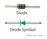
An electrical component called a diode can be used on circuit paths to govern the flow of current. They are a key component in basic transistorized voltage regulator circuits, as we’ll see later. For now, let’s get a basic understanding of how they work. Diodes are typically made of a semiconductor material, such as the element germanium. These materials behave in a complex way that fall along the lines of quantum physics. Esoteric phrases such as electron-hole theory, crystalline atomic lattice theory, and impurity doping are some of the concepts involved and would require a book onto themselves to explain. For the purposes of this article all we have to know is that semiconductors have two properties. The first property is that of an electrical conductor, that is, a material which allows electric current to pass through it. Copper wire is a good example of this. The second property is that of an electrical insulator, which blocks the flow of electric current. Materials such as glass, wood, and rubber fall into the insulator category. A photo of a diode is shown in Figure 1, along with its symbol used in electrical schematics.
Figure 1
When electric current flows through a diode in one direction, as shown in Figure 2, the semiconductor material inside of it acts as a conductor, ushering it along a single path.
Figure 2
When current tries to flow through the diode in the reverse direction, the semiconductor material acts as an insulator. That is, it blocks the flow of current as shown in Figure 3.
Figure 3
So we see that diodes can act like one way streets, restricting current flow. But, not all diodes work this way. Next week we’ll introduce a special kind of diode called the Zener diode, which allows current to flow in two different directions, and we’ll see how this functionality is put to work in regulated power supplies. ____________________________________________ |


Transistors – Voltage Regulation Part VII
Monday, September 3rd, 2012| Back when television had barely escaped the confines of black and white transmission there was a men’s clothing store commercial whose slogan still sticks in my mind, “Large and small, we fit them all.” It’s a nice concept, but unfortunately the same doesn’t always apply to electronic power supplies.
Last time we learned that when the electrical resistance changes on an unregulated power supply its output voltage changes proportionately. This makes it unsuitable for powering devices like microprocessor chips, which require an unchanging voltage to operate properly. Now let’s look at another shortcoming of unregulated power supplies, that being how one supply can’t fit both large and small voltage requirements. Figure 1 shows the components of a simple unregulated power supply.
Figure 1
The diagram illustrates the voltage changes taking place as electric current passes through the supply’s four components, which ultimately results in the conversion of 120 volts alternating current (VAC) into 12 volts direct current (VDC). First the transformer converts the 120 VAC from the wall outlet to the 12 volts required by most electronic devices. These voltages are shown at Points A and B. The voltage being put out by the transformer results in waves of energy which alternate between a positive maximum value, then to zero, and finally to a maximum negative value. But we want our power supply to produce 12 VDC. By VDC, I mean voltage that never falls to zero and stays at a positive 12 volts direct current consistently. This is when the diode bridge and capacitor come into play. The diode bridge consists of four electronic components, the diodes, which are connected together to form a bridge and uses semiconductor technology to transform negative voltage from the transformer into positive. The result is a series of 12 volt peaks as shown at Point C. But we still have the problem of zero voltage gaps between each peak. You see, over time the voltage at Point C of Figure 1 keeps fluctuating between 0 volts and positive 12 volts, and this is not suitable to power most electronics, which require a steady VDC current. We can get around this problem by feeding voltage from the diode bridge into the capacitor. When we do that, we eliminate the zero voltage gaps between the peaks. This happens when the capacitor charges up with electrical energy as the voltage from the diode bridge nears the top of a peak. Then, as voltage begins its dive back to zero the capacitor discharges its electrical energy to fill in the gaps between peaks. In other words it acts as a kind of reserve battery. The result is the rippled voltage pattern observed at Point D. With the current gaps filled in, the voltage is now a steady VDC. The output voltage of the unregulated power supply is totally dependant on the design of the transformer, which in this case is designed to convert 120 volts into 12 volts. This limits the power supply’s usefulness because it can only supply one output voltage, that being 12 VDC. This voltage may be insufficient for some electronics, like those often found in microprocessor controlled devices where voltages can range between 1.5 and 24 volts. Next time we’ll illustrate this limitation by revisiting our microprocessor control circuit example and trying to fit this unregulated power supply into it. ____________________________________________ |

Further Inside the Wall Wart
Sunday, September 11th, 2011| What do wall warts, aka AC wall adapters, and microwave ovens have in common? Well, in previous blogs discussing microwaves, we saw how a microwave oven’s high voltage circuitry uses a transformer, diode, and capacitor to effectively convert AC voltage into DC voltage. Wall warts do much the same thing and in very much the same way.
If you will recall from our discussion of microwave ovens in the past few weeks, the transformer in a high voltage circuit transforms 120 volts into a much higher voltage, say 4000 volts, in order to make things work. The diode and capacitor within both the microwave and the wall wart are key to facilitating this magical act, but in the wall wart it happens at a much lower voltage, about 12 volts. Last week we began exploring the inner workings of the wall wart. We discovered how its transformer converts the 120 volts emanating from your average wall outlet to the 12 volts required by most electronic devices. These voltages are shown at Points A and B in Figure 1 below. The fact that the voltage being put out results in waves of energy which alternate between a positive maximum value, zero, and a negative maximum value, makes it an unacceptable power source for most electronic devices. They require voltage that doesn’t alternate, and this is where the wall wart’s diode bridge and capacitor come into play.
Figure 1 – The Workings of the Wall Wart Transformer The wall wart’s diode bridge consists of four electronic components, namely the diodes, which are connected together. This diode bridge goes a bit further than the single diode present in a microwave oven, because it doesn’t merely eliminate negative aspects of alternating voltage. It actually transforms negative voltage into positive voltage. The result is a series of 12 volt peaks as shown at Point C of Figure 1. In fact, we end up with twice as many voltage peaks, and this is important, as you’ll see below. We still have the problem of zero voltage gaps to address. You see, over time the voltage at Point C of Figure 1 keeps changing between 0 volts and positive 12 volts. This can lead to problems, because many electronic devices require a consistent voltage of greater than zero to operate properly. For example, a light emitting diode (LED) might develop an annoying flicker, or you might end up hearing an irritating hum while listening to the radio. These annoyances are virtually eliminated by feeding voltage from the diode bridge into the capacitor, which gets rid of the zero voltage gaps between the voltage peaks. Like a microwave’s capacitor, the one within a wall wart charges up with electrical energy as the voltage from the diode bridge nears the top of a peak. Then, as voltage begins its dive back to a zero value, the capacitor discharges its electrical energy to fill in the gaps between peaks. The result is the rippled voltage pattern at Point D of Figure 1. With the gaps filled in, the voltage is at, or close enough to, the 12 volts required to keep an electronic device operating properly when it is connected to the wall wart’s low voltage power cord. Well, that’s it for our look at the wall warts that power our myriad of electronic devices. Next time we’ll switch to a totally topic and look at some of the basics of food manufacturing equipment design. ____________________________________________ |

Inside The Wall Wart
Monday, September 5th, 2011|
What would a cop show be without a crime scene, or better yet the obligatory dissection at the morgue? Forensic doctors performing autopsies have become commonplace, the clues they provide indispensable. Forensic engineers such as myself do much of the same thing, working our way backwards through time by dissecting industrial equipment and consumer products left in the wake of fires, injuries, and deaths. Let’s do some forensic dissecting now to see what’s in a wall wart and how it works. The inside of a basic wall wart is shown in Figure 1.
Figure 1 – Inside The Wall Wart You’ll note that a wall wart has four main components: a transformer, diode bridge, capacitor, and a printed circuit board (PCB). The PCB is constructed of plastic resin upon which is mounted copper strips. This makes a rigid platform base upon which electronic components are attached, namely the transformer, diode bridge, and capacitor. These components are soldered to the PCB, tying them together both mechanically and electrically. Now let’s see how the components of the wall wart work together to change the 120 volts coming from your standard wall outlet into the 12 volts needed to power a typical electronic device. We’ll use an instrument known as an oscilloscope to help us visualize what’s going on. See Figure 2.
Figure 2 – The Workings of the Wall Wart Transformer What is depicted in the graph above is the oscilloscope’s ability to receive an electronic signal, measure it, graph it, and then display it on a screen. This enables us to see how the signal changes over time. At Point A, which represents the wall wart plugged into a wall outlet, the voltage alternates between positive 120 volts and negative 120 volts upon entering the wall wart, which will now act as a transformer. The wall wart transformer then does as its name suggests, it transforms the 120 volts coming from the outlet into the 12 volts shown at Point B. You will note that this lower voltage also alternates between positive and negative values, just as the original 120 volts emanating from the wall outlet did. In one of my earlier blogs I explained that transformers only work when the electricity passing through them alternates over time. (Click here for a refresher: Transformers ) High voltage alternating electricity in one transformer coil creates magnetic fields that induce alternating electricity at a different voltage in a second transformer coil. So when you put alternating voltage into the transformer, you get alternating voltage out. But that’s not the end of the story. Many electronic devices operate on voltage that doesn’t alternate. What then? Will our handy wall wart still be able to bridge the electrical gap to fill our needs? Next time we’ll see how the diode bridge and capacitor come into play to deal with the alternating voltage from the transformer in a manner eerily similar to a microwave oven’s high voltage circuit. ____________________________________________ |


The Microwave Oven — More on How AC Becomes DC
Monday, August 15th, 2011| The world of electricity is full of mysteries and often unanticipated outcomes, and if you’ve been reading along with my blog series you have been able to appreciate and come to some understanding of a fair number of them. This week’s installment will be no exception.
Last week we looked briefly at the high voltage circuit within a microwave oven. We discovered that the circuit contains a transformer that raises 120 volts alternating current (AC) to a much higher voltage, around 4000 volts AC. The circuit then transforms the AC into direct current (DC) with the help of electronic components known as a diode and capacitor. Let’s take a closer look at how the diode and capacitor work together to make AC into DC. Let’s follow an AC wave with the aid of a device called an oscilloscope. An oscilloscope takes in an electronic signal, measures it, graphs it, and shows it on a display screen so you can see how the signal changes over time. An AC wave is shown in Figure 1 as it would appear on an oscilloscope. Figure 1 – Alternating Current Wave You can see that each wave cycle starts with a zero value, climbs to a positive maximum value, then back to zero, and finally back down to a maximum negative value. The current keeps alternating between positive and negative polarity, hence the name “alternating current.” Within the microwave oven’s high voltage circuitry the transformer does the job of changing, or transforming if you will, 120 volts AC into 4000 volts AC. This high voltage is needed to make electrons leave the cathode in the magnetron and move them towards the anode to generate microwaves. But we’re not done with the transformation process yet. The magnetron requires DC to operate, not AC. DC current remains constant over time, maintaining a consistent positive value as shown in Figure 2. It is this type of consistency that the magnetron needs to operate.
Figure 2 – Direct Current The microwave’s diode and capacitor work together to convert the 4000 volts AC into something which resembles 4000 volts DC. First the diode acts like a one-way valve, passing the flow of positive electric current and blocking the flow of negative current. It effectively chops off the negative part of the AC wave, leaving only positive peaks, as shown in Figure 3.
Figure 3 – The Diode Chops Off The Negative Part of the AC Wave Between the peaks are gaps where there is zero current, and this is when the capacitor comes into play. Capacitors are similar to batteries because they can be charged with electrical energy and then discharge that energy when needed. Unlike a battery, the capacitor charges and discharges very quickly, within a fraction of a second. Within the circuitry of a microwave oven the capacitor charges up at the top of each peak in Figure 3, then, when the current drops to zero inside the gaps the capacitor comes into play, discharging its electrical energy into the high voltage circuit. The result is an elimination of the zero current gaps. The capacitor acts as a reserve energy supply to fill in the gaps between the peaks and keep current continually flowing to the magnetron. We have now witnessed a mock DC current situation being created, and the result is shown in Figure 4.
Figure 4 – The Capacitor Discharges to Fill In The Gaps Between Peaks The output of this approximated DC current looks like a sawtooth pattern instead of the straight line of a true DC current shown in Figure 2. This ripple pattern is evidence of the “hoax” that has been played with the AC current. The net result is that the modified AC current, thanks to the introduction of the diode and energy storing capacitor, has made an effective enough approximation of DC current to allow our magnetron to get to work jostling electrons loose from the cathode and putting our microwave oven into action. You now have a basic understanding of how to turn AC into an effective approximation of DC current. Next week we’ll find out how this high voltage circuit can prove to be lethal, even when the microwave oven is unplugged. ____________________________________________ |


The Microwave Oven High Voltage Circuit—How AC Becomes DC
Sunday, August 7th, 2011| My mom was a female do-it-yourselfer. Toaster on the blink? Garbage disposal grind to a halt? She’d take them apart and start investigating why. Putting safety first, she always pulled the plug on electrical appliances before working on them. Little did she know that this safety precaution would not be enough in the case of a microwave oven. Let’s see how even an unplugged microwave can prove to be a lethal weapon and, yes, we’re going to have to get technical.
Last week we talked about the magnetron and how it needs thousands of volts to operate. To get this high of a voltage out of a 120 volt wall outlet–the voltage that most kitchen outlets provide–the microwave oven is equipped with electrical circuitry containing three important components: a transformer, a diode, and a capacitor, and just like the third rail of an electric railway system these items are to be avoided. If you decide to take your microwave oven apart and you come into contact with high voltage that is still present, you run the risk of injury or even death. But how can high voltage be present when it’s unplugged? Read on. First we need to understand how the 120 volts emitting from your wall outlet becomes the 4000 volts required to power a microwave’s magnetron. This change takes place thanks to a near magical act performed by AC, or alternating current. In the case of our microwave components, specifically its diode and capacitor, AC is made to effectively mimic the power of DC, or direct current, the type of current a magnetron needs. This transformation is made possible through the storage of electrical energy within the microwave’s capacitor. Next week we’ll examine in detail how this transformation from AC to DC current takes place, as seen through a device called an oscilloscope. ____________________________________________
|


