Posts Tagged ‘drive belt’

A First Look at the Euler-Eytelwein Formula

Friday, May 5th, 2017

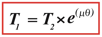
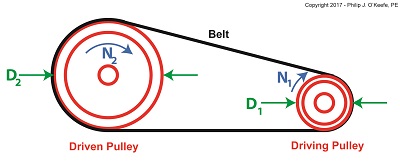
    Last time we introduced the Pulley Speed Ratio Formula, a Formula which assumes a certain amount of friction in a pulley-belt assembly in order to work.   Today we’ll introduce another Formula, one which oversees how friction comes into play between belts and pulleys, the Euler-Eytelwein Formula.   It’s a Formula developed by two pioneers of engineering introduced in an earlier blog, Leonhard Euler and Johann Albert Eytelwein.

    Here again is the Pulley Speed Ratio Formula,

D1 × N1 = D2 × N2

where, D1 is the diameter of the driving pulley and D2 the diameter of the driven pulley. The pulleys’ rotational speeds are represented by N1 and N2.

   This equation works when it operates under the assumption that friction between the belt and pulleys is, like Goldilock’s preferred bed, “just so.”   Meaning, friction present is high enough so the belt doesn’t slip, yet loose enough so as not to bring the performance of a rotating piece of machinery to a grinding halt.

    Ideally, you want no slippage between belt and pulleys, but the only way for that to happen is if you have perfect friction between their surfaces—something that will never happen because there’s always some degree of slippage.   So how do we design a pulley-belt system to maximize friction and minimize slip?

    Before we get into that, we must first gain an understanding of how friction comes into play between belts and pulleys.   To do so we’ll use the famous Euler-Eytelwein Formula, shown here,

A First Look at the Euler-Eytelwein Formula

A First Look at the Euler-Eytelwein Formula


where, T1 and  T2 are belt tensions on either side of a pulley.

    We’ll continue our exploration of the Euler-Eytelwein Formula next time when we discuss the significance of its two sources of tension.

Copyright 2017 – Philip J. O’Keefe, PE

Engineering Expert Witness Blog

____________________________________


A Pulley Speed Ratio Formula Application

Friday, April 21st, 2017

    Last time we saw how pulley diameter governs speed in engineering scenarios which make use of a belt and pulley system.   Today we’ll see how this phenomenon is defined mathematically through application of the Pulley Speed Ratio Formula, which enables precise pulley diameters to be calculated to achieve specific rotational speeds.   Today we’ll apply this Formula to a scenario involving a building’s ventilating system.

    The Pulley Speed Ratio Formula is,

                                                D1 × N1 =  D2 × N2                             (1)

where, D1 is the diameter of the driving pulley and D2 the diameter of the driven pulley.

A Pulley Speed Ratio Formula Application

A Pulley Speed Ratio Formula Application


The pulleys’ rotational speeds are represented by N1 and N2,  and are measured in revolutions per minute (RPM).

    Now, let’s apply Equation (1) to an example in which a blower must deliver a specific air flow to a building’s ventilating system.   This is accomplished by manipulating the ratios between the driven pulley’s diameter, D2, with respect to the driving pulley’s diameter, D1.   If you’ll recall from our discussion last time, when both the driving and driven  pulleys have the same diameter, the entire assembly moves at the same speed, and this would be bad for our scenario.

    An electric motor and blower impeller moving at the same speed is problematic because electric motors are designed to spin at much faster speeds than typical blower impellers in order to produce desired air flow.   If their pulleys’ diameters were the same size, it would result in an improperly working ventilating system in which air passes through the furnace heat exchanger and air conditioner cooling coils far too quickly to do an efficient job of heating or cooling.

    To bear this out, let’s suppose we have an electric motor turning at a fixed speed of 3600 RPM and a belt-driven blower with an impeller that must turn at 1500 RPM to deliver the required air flow according to the blower manufacturer’s data sheet.   The motor shaft is fitted with a pulley 3 inches in diameter.   What pulley diameter do we need for the blower to turn at the manufacturer’s required 1500 RPM?

    In this example known variables are D1 = 3 inches, N1 = 3600 RPM, and N2 = 1500 RPM.   The diameter D2 is unknown.   Inserting the known values into equation (1), we can solve for D2,

                               (3 inches) × (3600 RPM) = D2 × (1500 RPM)         (2)

Simplified, this becomes,

                                            D2 = 7.2 inches                                      (3)

    Next time we’ll see how friction affects our scenario.


Copyright 2017 – Philip J. O’Keefe, PE

Engineering Expert Witness Blog

____________________________________