|
We’ve been discussing torque and how it enables more power to be available to applications such as loosening tight nuts with a wrench. Now we’ll see how those same principles apply to another application, a simple gear train. To review, the torque formula is, Torque = Distance × Force × sin(ϴ) where, Distance and Force are vector magnitudes and ϴ is the angle formed between them.
Referring to the gear train illustration above, we see that Force and Distance vectors are present, just as they had been in our previous wrench/nut example. But instead of torque being created by way of force that’s applied to a wrench, things are reversed, and it’s the torque that creates the force. You see, in the wrench/nut example, the force applied to the wrench handle created torque on the nut. In our present gear train example, the torque applied to the motor shaft is created by an electric motor exerting pressure upon the motor shaft, which in turn exerts a force upon the driving gear teeth. The driving gear is also attached to this shaft, so torque causes the driving gear to rotate along with the motor. This rotation results in a force being exerted at the point where the teeth of the driving gear mesh with the teeth of the driven gear. In other words, in the wrench/nut example force created torque, while in the present example torque creates a force. The gear train has a pivot point, as there was in our wrench/nut example, but this time it’s located at the center of the motor shaft rather than at the center of a nut. The pivot point in both examples is where the action takes place. The motor’s shaft and driving gear rotate around it, just as the wrench jaws and handle rotated around the nut’s pivot point. In both examples, the Distance vectors extend out from the pivot points to meet up with the Force vector’s path. In the gear train example, this Force vector path is called a line of action, as introduced earlier in this blog series. This line of action passes through to the point where the driving and driven gear teeth mesh. The force acting upon that point causes the gears in the gear train to rotate, and as they turn mechanical energy is transferred from the motor to whatever machinery component is attached to the shaft of the driven gear. The powered component will then be able to perform useful work such as cutting lumber, mixing frosting for a cake, drilling holes in steel, or propelling vehicles. You will note that there is an angle ϴ which exists between the Distance and Force vectors. Since we have a pivot point, a Force vector, a Distance vector, and an angle ϴ, we are able to apply the torque formula to gear trains exactly as we did in our wrench/nut example. We can then use that formula to calculate how torque is transmitted between gears in the train. Next time we’ll examine the distance and force vectors in a simple gear train. _______________________________________ |
Posts Tagged ‘driven gear’
Torque and Force
Tuesday, April 29th, 2014
Gear Reduction Worked Backwards
Sunday, March 9th, 2014|
Last time we saw how a gear reduction does as its name implies, reduces the speed of the driven gear with respect to the driving gear within a gear train. Today we’ll see how to work the problem in reverse, so to speak, by determining how many teeth a driven gear must have within a given gear train to operate at a particular desired revolutions per minute (RPM). For our example we’ll use a gear train whose driving gear has 18 teeth. It’s mounted on an alternating current (AC) motor turning at 3600 (RPM). The equipment it’s attached to requires a speed of 1800 RPM to operate correctly. What number of teeth must the driven gear have in order to pull this off? If you’ve identified this to be a word problem, you’re correct.
Let’s first review the gear ratio formulas introduced in my previous two articles: R = nDriving ÷ nDriven (1) R = NDriven ÷ NDriving (2) Our word problem provides us with enough information so that we’re able to use Formula (1) to calculate the gear ratio required: R = nDriving ÷ nDriven = 3600 RPM ÷ 1800 RPM = 2 This equation tells us that to reduce the speed of the 3600 RPM motor to the required 1800 RPM, we need a gear train with a gear ratio of 2:1. Stated another way, for every two revolutions of the driving gear, we must have one revolution of the driven gear. Now that we know the required gear ratio, R, we can use Formula (2) to determine how many teeth the driven gear must have to turn at the required 1800 RPM: R = 2 = NDriven ÷ NDriving 2 = NDriven ÷ 18 Teeth NDriven = 2 × 18 Teeth = 36 Teeth The driven gear requires 36 teeth to allow the gear train to operate equipment properly, that is to say, enable the gear train it’s attached to provide a speed reduction of 1800 RPM, down from the 3600 RPM that is being put out from the driving gear. But gear ratio isn’t just about changing speeds of the driven gear relative to the driving gear. Next time we’ll see how it works together with the concept of torque, thus enabling small motors to do big jobs.
_______________________________________ |

Gear Reduction
Wednesday, March 5th, 2014|
Last time we learned there are two formulas used to calculate gear ratio, R. Today we’ll see how to use them to calculate a gear reduction between gears in a gear train, a strategy which enables us to reduce the speed of the driven gear in relation to the driving gear. If you’ll recall from last time, our formulas to determine gear ratio are: R = NDriven ÷ NDriving (1) R = nDriving ÷ nDriven (2) Now let’s apply them to this example gear train to see how a gear reduction works.
Here we have a driven gear with 23 teeth, while the driving gear has 18. For our example the electric motor connected to the driving gear causes it to turn at a speed, nDriving, of 3600 revolutions per minute (RPM). Knowing these numerical values we are able to determine the driven gear speed, nDriven. First we’ll use Formula (1) to calculate the gear ratio using the number of teeth each gear has relative to the other: R = NDriven ÷ NDriving R = 23 Teeth ÷ 18 Teeth R = 1.27 In gear design nomenclature, the gear train is said to have a 1.27 to 1 ratio, commonly denoted as 1.27:1. This means that for every tooth on the driving gear, there are 1.27 teeth on the driven gear. Interestingly, the R’s in both equations (1) and (2) are identical, and in our situation is equal to 1.27, although it is arrived at by different means. In Formula (1) R is derived from calculations involving the number of teeth present on each gear, while Formula (2)’s R is derived by knowing the rotational speeds of the gears. Since R is the common link between the two formulas, we can use this commonality to create a link between them and insert the R value determined in one formula into the other. Since we have already determined that the R value is 1.27 using Formula (1), we can replace the R in Formula (2) with this numerical value. As an equation this looks like: R = 1.27 = nDriving ÷ nDriven Now all we need is one more numerical value to solve Formula (2)’s equation. We know that the speed at which the driving gear is rotating, nDriving , is 3600 RPM. We use basic algebra to calculate the driven gear speed, nDriven : 1.27 = 3600 RPM ÷ nDriven nDriven = 3600 RPM ÷ 1.27 = 2834.65 RPM Based on our calculations, the driven gear is turning at a speed that is slower than the driving gear. To determine exactly how much slower we’ll calculate the difference between their speeds: nDriving – nDriven = 3600 RPM – 2834.65 RPM ≈ 765 RPM So in this gear reduction the driven gear turns approximately 765 RPM slower than the driving gear. Next time we’ll apply a gear reduction to a gear train and see how to arrive at a particular desired output speed. _______________________________________ |

Gear Ratio Formulas
Sunday, February 23rd, 2014|
Last time we introduced a way to convert individual gear speeds in relation to one another within a gear train by employing a conversion tool known as the gear ratio. Today we’ll introduce the gear ratio formulas, of which there are two types.
The first formula for determining gear ratio is based on knowing the driving gear revolutions per minute (RPM), notated as nDriving, and the driven gear RPM, nDriven. Given that knowledge we can calculate the gear ratio, R, that exists between them by the formula: R = nDriving ÷ nDriven (1) The other way to determine gear ratio, R, is by knowing the number of teeth on both the driving gear, NDriving, and the driven gear, NDriven. That’s right, it all boils down to simply counting the number of teeth on each gear. In this instance the gear ratio is calculated by the following formula: R = NDriven ÷ NDriving (2) Equations (1) and (2) may look virtually identical, but they’re not. In mechanical engineering calculations, lower case n is typically used to denote the RPM of rotating objects such as shafts, wheels, pulleys, and gears. Upper case N is typically used to denote the number of teeth on a gear. Next time we’ll see how to manipulate these two equations so as to arrive at a particular gear ratio. _______________________________________ |

When Do You Need To Modify Gear Ratio?
Wednesday, February 19th, 2014|
Last time we saw how the involute profile of spur gear teeth ensures smooth contact between gears when they rotate. Today we’ll see why it’s important to be able to change the rotational speed of the driven gear in relation to that of the driving gear by modifying their gear ratio, the speeds at which gears move relative to one another. Why would we want to modify the rotational speeds of gears relative to one another? One reason is to compensate for the fact that alternating electric current (AC) motors drive most modern machinery, and these motors operate at a fixed speed determined by the 60 cycles per second frequency of electricity provided by the utility power grids of North America. By fixed speed I mean that the motor’s shaft revolves at a single, fixed rate. It can’t run any faster or slower. This is fine for some motorized applications, but not others. Basic machinery such as wood cutting saws, grinders, and blowers function well within the parameters of the AC motor’s fixed speed, because their working parts are intended to rotate at the same rate as the motor’s shaft. As a matter of fact, in this instance there’s often no need for a gear train, because the working parts can be connected directly to the motor’s shaft, and the machinery will be powered and function correctly. There are many instances however in which a fixed speed does not match the speed required for more complex machinery to correctly perform precise, specialized tasks. Take a machine tool meant to cut steel bars, for example. It has a rotating part meant to cut through the steel during machining, and to properly do so its cutting tool bit must turn at 400 revolutions per minute (RPM). If it turns any faster, the cut won’t be smooth and the tool bit will overheat and break due to increased friction. If the AC motor driving the machine tool turns at 1750 RPM, a common speed for such motors, then the tool bit will be turning at a much faster rate than the desired 400 RPM, and this presents a problem. To solve the problem we need only add a gear train between the motor and the part containing the tool bit, meaning, we must connect the gear train’s driving gear to the motor’s shaft and a driven gear to the part’s shaft. But in order for this arrangement to work a conversion must take place, that is, we must design the gear train to operate at a specific gear ratio. By gear ratio, I mean the speeds at which the two gears will rotate relative to one another. Next time we’ll introduce the gear ratio formulas that make it all work.
_______________________________________
|

Spur Gears In Motion
Wednesday, February 12th, 2014|
Last time we learned about forces generated when spur gear teeth mesh and move along a specific line of action. Today we’ll see them in movement. Looking at the illustration below it might appear that there are three teeth in contact, but this isn’t the case. As the gears rotate, only two teeth make contact at any given time, although the third tooth comes very close. The actual point of contact between the teeth is represented by a black dot on the illustration below. This is where two opposing forces, F1 and F2, meet.
Now let’s animate the illustration to see how the line of action remains constant the entire time the gear teeth are in motion. By constant I mean that this imaginary line’s position and angle does not change relative to the gears throughout the course of their movement.
In the animation, the point of contact moves along the line of action as the gears turn. Each tooth’s involute profile ensures that smooth contact is maintained along the faces and flanks of the gear teeth. The involute profile’s unique shape facilitates opposing teeth remaining in constant contact along the line of action for the duration of their movement together. If the gear tooth profile wasn’t involute in its shape, say for example it was square or triangular, the forces acting upon the meshed teeth during movement would vary in direction and intensity as a result of uneven contact between the teeth. For example, consider the square shaped tooth profile in the gear train below.
As the gears rotate, the pointed tip of one tooth strikes the flat face of another. As they continue to turn, the two flat faces of the teeth slap together, then the pointed tip of one tooth will strike the flat face of the other tooth, and so forth. The result is movement that is jerky and destructive. There would be excessive vibration and wear and tear on the teeth, resulting in rapid gear tooth erosion and decreased efficiency overall. Next time we’ll introduce the gear ratio, a formula which allows us to alter the rotational speed of the driven gear in relation to that of the driving gear, something which comes in handy when designing things that require this differential.
_______________________________________ |


Overcoming Inertia
Monday, February 3rd, 2014|
Inertia. It’s the force that keeps us in bed after the alarm has rung. It seems to have a life of its own, and today we’ll see how it comes into play in keeping other stationary objects at rest. Last time we identified a specific point of contact between spur gear teeth in a gear train and introduced the opposing forces, F1 and F 2, generated there. Today we’ll see what these forces represent, identifying one of them as inertia.
So where do these forces come from? They’re forces generated by different means that converge at the same point of contact, the point at which gear teeth mesh. They follow a very specific geometric path to meet there, an imaginary straight line referred to as the line of action. F1 is always generated by a source of mechanical energy. In our locomotive example introduced earlier in this blog series that source is an electric traction motor, upon which a driving gear is mounted. When the motor is energized, a driving force F1 is generated, which causes gear teeth on the driving gear to push against gear teeth of the driven gear. Force F2 is not as straightforward to understand, because it’s not generated by a motor. Instead, it’s the resisting force that the weight of a stationary object poses against its being moved from an at-rest position, known as inertia. The heavier the object, the more inertia it presents with. Trains, of course, are extremely heavy, and to get them to move a great deal of inertia must be overcome. Inertia is also a factor in attempting to stop objects already in motion. To get a stationary locomotive to move, mechanical energy must be transmitted from the driving gear that’s attached to its traction motor, then on to the driven gear attached to its axle. At their point of contact, the driving force of the motor, F1, is met by the resisting force of inertia, F2. In order for the train to move, F1 must be greater than F2. If F1 is less than or equal to F2, then the train won’t leave the station. Next week we’ll animate our static image and watch the interplay between gear teeth, taking note of the line of action during their movement.
_______________________________________ |

Meshed Gear Teeth and Their Point of Contact
Monday, January 27th, 2014|
Last time we learned that the geometric shape specific to spur gear teeth is known as an involute profile. Today we’ll look at the geometry behind this profile and the very specific place at which gear teeth meet, known as the point of contact. The transmission of mechanical energy between meshed gears may seem on its face to be straightforward, after all their gears are interlaced and interact with one another. But their interaction involves some rather complex geometry, because forces are directed in a peculiar fashion between the teeth of the driving and driven gears. Let’s consider the following illustration to get a better understanding.
 Meshed Gear Tooth Geometry
As we learned previously in this series, the pitch circle of a gear is an imaginary arc passing through each tooth between their top and bottom lands. The pitch circles of the driving and driven gears are represented by heavy red dashed lines in the illustration. To ensure proper alignment and smooth action between gear teeth during rotation, the gears are spaced so that their pitch circles just meet but never intersect. This specific point is known as the point of contact. It is the only point at which gears will come into actual physical contact with one another, and it provides just enough contact so that when the driving gear turns in one direction, say clockwise, its teeth exert pressure upon the driven gear teeth, forcing it to move in the opposite direction, counterclockwise. The forces which come into play at the point of contact are represented in the illustration by a black dot with oppositional blue arrows extending from it. These arrows represent the opposing mechanical forces, F1 and F2 , which act upon the teeth when they make contact. We’ll learn more about the effect of those forces next time when we follow a locomotive from a stationary position into one of movement.
_______________________________________ |
Spur Gear Tooth Geometry and the Involute Curve
Sunday, January 19th, 2014|
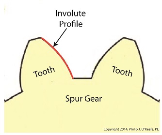
Last time we learned how spur gears mesh together to form a gear train and we examined a train consisting of just two gears, one being the driving gear, the other the driven gear. Today we’ll take a look at the geometry behind the smooth functioning of modern spur gear teeth when we identify their peculiar shape to be that of an involute curve. The curved profile of spur gear teeth conforms to a type of mathematical curve found in geometry known as an involute. The involute profile of a spur gear tooth is shown in red below. The mathematical notion of the involute was first presented in 1673 by Dutch mathematician Christiaan Huygens, in his book, Horologium Oscillatorium. Huygens’ book presents his studies on clock pendulums and the applied mathematics he used in an effort to predict their often erratic motion on ships at sea. His book ultimately dealt with far more than this, resulting in a treatise on the mathematical properties of the involutes of curves. To see how an involute curve is formed, we’ll conduct a simple experiment. One end of string is attached with a tack to a circular object, like the yellow rod shown in the following illustration. The other end of string has a red ball attached to it.
 Forming An Involute Curve If we grab the ball and pull the string taught while wrapping the string around the rod, the ball’s path will form an involute curve due to the incremental shortening of the string that occurs as it wraps around the rod. Next time we’ll see how the involute profile of gear teeth contributes to efficient mechanical energy transmission in gear trains. _______________________________________ |

Gear Trains
Monday, January 13th, 2014|
Last time we covered the basic terminology of spur gears. Today we’ll see how they interact with one another to form a gear train, such as the one depicted below.
 Meshing Spur Gears Form A Gear Train A gear train is formed when the teeth of two or more gears mesh and work together for the purpose of powering a mechanical device. A gear train can consist of as little as two gears, but trains can be so large as to contain dozens of gears, depending on the complexity of the device they are powering. But no matter how many gears are employed, there are certain key features that are shared by every gear train assembly. First, one gear within the train must be attached to a shaft rotated by a source of mechanical energy, such as an engine or electric motor. This gear is called the driving gear. The second requirement of a gear train is that at least one gear other than the driving gear is mounted to the shaft of a rotating machine part. This gear is called the driven gear.
 Locomotive Gear Train Consisting Of Two Gears The illustration above shows an exploded view of a locomotive gear train assembly consisting of two gears. The driving gear is mounted to the shaft of an electric traction motor. The driven gear is mounted to the locomotive’s axle. When a motor is attached to the axle, the two gears mesh together. The traction motor converts electrical energy into mechanical energy, which is supplied to the driving gear via the spinning motor’s shaft. The teeth of the driving gear then transmit the motor’s mechanical energy to the teeth of the driven gear, which then turn the locomotive’s wheels. It’s just one of countless operations that can be performed with gear train assemblies. Next time we’ll examine the geometry behind modern spur gear tooth design. _______________________________________ |


