Posts Tagged ‘driven pulley’

The Two T’s of the Euler-Eytelwein Formula

Sunday, May 14th, 2017

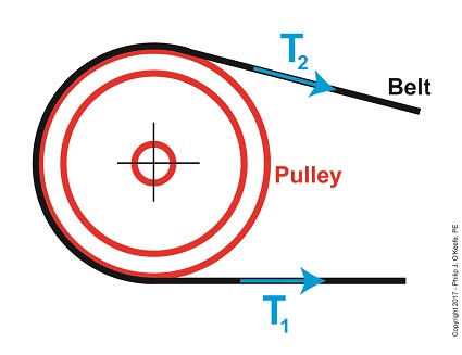
    Last time we introduced some of the variables in the Euler-Eytelwein Formula, an equation used to examine the amount of friction present in pulley-belt assemblies.   Today we’ll explore its two tension-denoting variables, T1 and T2.

   Here again is the Euler-Eytelwin Formula,where, T1 and  T2 are belt tensions on either side of a pulley,

T1 = T2 × eθ)

    T1 is known as the tight side tension of the assembly because, as its name implies, the side of the belt containing this tension is tight, and that is so due to its role in transmitting mechanical power between the driving and driven pulleys.   T2 is the loose side tension because on its side of the pulley no mechanical power is transmitted, therefore it’s slack–it’s just going along for the ride between the driving and driven pulleys.

   Due to these different roles, the tension in T1 is greater than it is in T2.

The Two T’s of the Euler-Eytelwein Formula

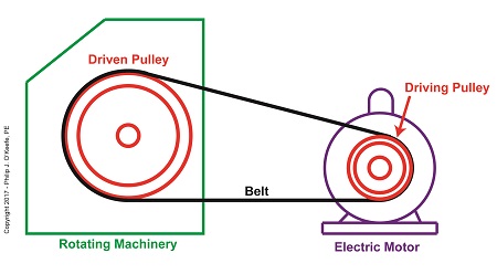
The Two T’s of the Euler-Eytelwein Formula

    In the illustration above, tension forces T1 and T2 are shown moving in the same direction, because the force that keeps the belt taught around the pulley moves outward and away from the center of the pulley.

    According to the Euler-Eytelwein Formula, T1 is equal to a combination of factors:  tension T2 ; the friction that exists between the belt and pulley, denoted as μ; and how much of the belt is in contact with the pulley, namely θ.

    We’ll get into those remaining variables next time.

Copyright 2017 – Philip J. O’Keefe, PE

Engineering Expert Witness Blog

____________________________________


A Pulley Speed Ratio Formula Application

Friday, April 21st, 2017

    Last time we saw how pulley diameter governs speed in engineering scenarios which make use of a belt and pulley system.   Today we’ll see how this phenomenon is defined mathematically through application of the Pulley Speed Ratio Formula, which enables precise pulley diameters to be calculated to achieve specific rotational speeds.   Today we’ll apply this Formula to a scenario involving a building’s ventilating system.

    The Pulley Speed Ratio Formula is,

                                                D1 × N1 =  D2 × N2                             (1)

where, D1 is the diameter of the driving pulley and D2 the diameter of the driven pulley.

A Pulley Speed Ratio Formula Application

A Pulley Speed Ratio Formula Application


The pulleys’ rotational speeds are represented by N1 and N2,  and are measured in revolutions per minute (RPM).

    Now, let’s apply Equation (1) to an example in which a blower must deliver a specific air flow to a building’s ventilating system.   This is accomplished by manipulating the ratios between the driven pulley’s diameter, D2, with respect to the driving pulley’s diameter, D1.   If you’ll recall from our discussion last time, when both the driving and driven  pulleys have the same diameter, the entire assembly moves at the same speed, and this would be bad for our scenario.

    An electric motor and blower impeller moving at the same speed is problematic because electric motors are designed to spin at much faster speeds than typical blower impellers in order to produce desired air flow.   If their pulleys’ diameters were the same size, it would result in an improperly working ventilating system in which air passes through the furnace heat exchanger and air conditioner cooling coils far too quickly to do an efficient job of heating or cooling.

    To bear this out, let’s suppose we have an electric motor turning at a fixed speed of 3600 RPM and a belt-driven blower with an impeller that must turn at 1500 RPM to deliver the required air flow according to the blower manufacturer’s data sheet.   The motor shaft is fitted with a pulley 3 inches in diameter.   What pulley diameter do we need for the blower to turn at the manufacturer’s required 1500 RPM?

    In this example known variables are D1 = 3 inches, N1 = 3600 RPM, and N2 = 1500 RPM.   The diameter D2 is unknown.   Inserting the known values into equation (1), we can solve for D2,

                               (3 inches) × (3600 RPM) = D2 × (1500 RPM)         (2)

Simplified, this becomes,

                                            D2 = 7.2 inches                                      (3)

    Next time we’ll see how friction affects our scenario.


Copyright 2017 – Philip J. O’Keefe, PE

Engineering Expert Witness Blog

____________________________________


Pulley Diameter Determines Speed

Saturday, April 8th, 2017

    Soon after the first pulleys were used with belts to transmit mechanical power, engineers such as Leonhard Euler and Johann Albert Eytelwein discovered that the diameter of the pulleys used determined the speed at which they rotated.   This allowed for a greater diversity in mechanical applications.   We’ll set up an examination of this phenomenon today.

    Last time we introduced this basic mechanical power transmission system consisting of a driving pulley, a driven pulley, and a belt, which we’ll call Situation A.

 A Driven Pulley’s Larger Diameter Determines a Slower Speed

A Driven Pulley’s Larger Diameter Determines a Slower Speed


    In this situation, the rotating machinery’s driven pulley diameter is larger than the electric motor’s driving pulley diameter.   The result is the driven pulley turns at a slower speed than the driving pulley.

    Now let’s say we need to speed the rotating machinery up so it produces more widgets per hour.   In that case we’d make the driven pulley smaller, as shown in Situation B.

 A Driven Pulley’s Smaller Diameter Determines a Faster Speed

A Driven Pulley’s Smaller Diameter Determines a Faster Speed


    With the smaller diameter driven pulley, the rotating machinery will operate faster than it did in Situation A.

    Next week we’ll introduce the Pulley Speed Ratio Formula, which mathematically defines this phenomenon.

 Copyright 2017 – Philip J. O’Keefe, PE

Engineering Expert Witness Blog

____________________________________


The Difference Between Driven and Driving Pulleys

Friday, March 31st, 2017

    Last time we introduced two historical legends in the field of engineering who pioneered the science of mechanical power transmission using belts and pulleysLeonhard Euler and Johann Albert Eytelwein.   Today we’ll build a foundation for understanding their famous Euler-Eytelwein Formula through our example of a simple mechanical power transmission system consisting of two pulleys and a belt, and in so doing demonstrate the difference between driven and driving pulleys.

    Our example of a basic mechanical power transmission system consists of two pulleys connected by a drive belt.   The driving pulley is attached to a source of mechanical power, for example, the shaft of an electric motor.   The driven pulley, which is attached to the shaft of a piece of rotating machinery, receives the mechanical power from the electric motor so the machinery can perform its function.

The Difference Between Driven and Driving Pulleys

The Difference Between Driven and Driving Pulleys 


    Next time we’ll see how driven pulleys can be made to spin at different speeds from the driving pulley, enabling different modes of operation in mechanical devices.

Copyright 2017 – Philip J. O’Keefe, PE

Engineering Expert Witness Blog

____________________________________