|
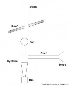
We’ve been talking about mechanical filtration, like the type used by fish tanks. Now we’ll consider another type, the “cyclone.” It’s something which most of us have become very familiar with, thanks to a British bloke and his awesome vacuum that “…won’t lose suction!” His invention makes use of the principles of cyclone technology, and as effective as it is used in vacuums, it’s equally impressive used in local exhaust ventilation system applications. A cyclone that has been incorporated within this type of system is shown in Figure 1. Figure 1 – Local Exhaust Ventilation System With Cyclone Here’s how it works. A local exhaust ventilation system draws in corrupted air by means of a strategically placed hood, and its fan pulls the captured air and dust mixture through ductwork and into the cyclone. The cyclone is shaped like a cone standing upright on its small end. A cutaway view is shown in Figure 2. Figure 2 – Cutaway View of a Cyclone When a quickly-moving air and dust mixture gets drawn into the cyclone by the fan, the mixture is forced to spiral down into the cone by the shape of the inlet passage. Because dust particles are heavier than air molecules, they tend to separate due to centrifugal force. The heavier dust particles are sent crashing into the sloping sides of the cone. They then slide down to the bottom of the cone, where they will eventually fall through the bottom and into a waiting trash bin. The lighter air tends to stay in the center of the cyclone and is eventually drawn out by the fan through the outlet passage. Unfortunately, cyclones are not 100% efficient when it comes to removing dust from the air. Their efficiency depends on many factors, including the shape of the cyclone, the speed of the flow going through it, and the weight of the dust particles. In any case, there’s always going to be some dust that will escape along with the air that’s being exhausted to the building’s exterior through the exhaust stack. If necessary, this air can be cleaned further before being released into the atmosphere by the use of additional filtration located within the ductwork between the cyclone and the fan. That wraps up our discussion on dust removal through mechanical filtration. Next time we’ll look at systems capable of removing chemical vapors. _____________________________________________ |
Posts Tagged ‘duct’
Industrial Ventilation – Local Exhaust Ventilation Filters and Air Cleaners II
Monday, May 9th, 2011Industrial Ventilation – Local Exhaust Ventilation Filters and Air Cleaners
Sunday, May 1st, 2011|
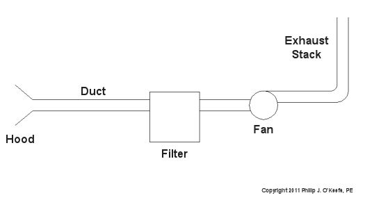
My wife is an aquarist, meaning she keeps aquariums. Three of them. Each contains a different variety of fish housed within its own unique liquid environment. One of these is a 35 gallon tank containing three goldfish. These fish have two unique characteristics that make them especially noteworthy, they are extremely hardy and extremely dirty. Hardly a week can go by between tank changes before the water quality starts to deteriorate, evidenced by cloudy, stinky water. It’s the kind of stink that makes a passerby in the area exclaim, “Who used the bathroom and didn’t turn on the exhaust fan!” Thank goodness for activated carbon. With its proper placement inside the aquarium’s filtration system a cleaner, fresher environment is delivered, both to fish inside the tank and the humans who watch them from outside. Put the carbon in the wrong compartment, however, and the water quality plummets back to its original fetid state within a matter of days. As is true with the proper care of goldfish, it is often necessary within an industrial environment to remove contaminants before the air that contains them is once again dispersed into the general environment. This is where filters and air cleaners come in. They’re generally placed inside the ductwork, somewhere between the hood and fan. Their job is to ensure a good, clean outcome, usually through an external exhaust of some sort. Local exhaust ventilation systems begin with a precisely positioned hood at the source of contamination and end with an exhaust stack located outside the building. Some airborne contaminants being released from the stack are deemed unsafe for the environment, and outdoor air quality standards promulgated by state and federal Environmental Protection Agencies limit their release back into the atmosphere. For this reason the proper use of filtration and air cleaners is crucial. Airborne contaminants are in the form of dusts and vapors. If the issue to be addressed comes in the form of dust, then filters and mechanical separators are commonly used. Filters, like the atmospheric conditions they are meant to address, come in many configurations. They are typically positioned within the local exhaust ventilation system ductwork, as shown in Figure 1 below. Figure 1 – Local Exhaust Ventilation System With Filter The fan draws in air and dust through the strategically positioned hood, located at the source of contamination, then follows a course through ductwork, passing through a filter along the way. The filter contains media with holes tiny enough to allow for air to pass through, but small enough to stop dust particles. The cleaned air is then drawn out of the filter by a fan, which finally exhausts it into an externally positioned stack. Next time we’ll continue our discussion on filtration devices by examining a cyclone. And no, I don’t mean the famous vacuum cleaner, although the methodology is similar. _____________________________________________ |
Industrial Ventilation – Local Exhaust Ventilation Ductwork
Monday, April 25th, 2011| Ever venture into your basement and stare in amazement at the labyrinth of ductwork stemming off from the furnace? Believe it or not, there’s a science behind that spaghetti bowl configuration. Ductwork can either be flexible or rigid, square or round in shape. Its job in a local exhaust ventilation system is to carry airborne contaminants from the originating source, the carefully positioned hood in the workplace, to the exhaust stack where it is vented outside the building. This job isn’t an easy one. Fluids, like air thick with toxins and toxic gases, don’t want to flow very well through ductwork unless you make their path as unimpeded as possible.
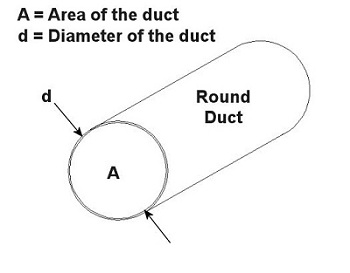
You can think of the air and contaminants flowing through ductwork as if it were like a car moving down a highway. Expressways don’t have sharp 90 degree turns or abrupt changes in width. These would cause a slow down in traffic, unless of course an accident is in the way. Expressways also tend to be rather large thoroughfares. The science behind ductwork follows the same basic principles to work effectively. It will minimize or eliminate sharp turns and it will avoid any abrupt changes in diameter. It will also be as wide in diameter as the environment will accommodate in order to move air volume most effectively. A local exhaust ventilation system’s performance can be greatly hampered and workers exposed to hazards if ductwork leaks. And if the leaks are upstream of the fan and large enough, they can reduce the ability of the local exhaust ventilation system to draw the airborne contaminants into the hood. Air starts getting drawn in through the leaks rather than through the hood. If the leaks are downstream of the fan, the airborne contaminants can re-enter the work area through the leaks rather than going outside through the exhaust stack. Ducts come in an endless variety of diameters, the diameter being part of a simple mathematical equation relating to flow velocity. In the simplest of terms, the flow of air through ductwork is governed by the following equation: Q = V × A where Q is the flow rate of air through the duct in cubic feet per minute (CFM), V is velocity of the air flow in feet per minute, and A is the cross sectional area of the duct in square feet. As an example, suppose you want to design a local exhaust ventilation system with ducts no greater than 5 inches in diameter because of space and clearance limitations. You want to use round ducts for the system because they handle air more efficiently and have no sharp corners where dust can collect. If an industrial hygienist determines that the air is required to flow at a minimum of 800 feet per minute through the duct, what is the airflow rate through the duct? Well, since we are dealing with a round duct, its cross sectional area is that of a circle: A = (π × d2) ÷ 4 where d is the diameter of the inside of the duct as shown in Figure 1 below. Figure 1 – Cross Section of a Round Duct So to use this equation for area, to solve for Q, then we must first convert the duct diameter from inches to feet, which makes our equation look like this: 5 inches ÷ 12 inches per foot = 0.416 feet This gives us a duct cross sectional area of: A = (π × (0.416 feet) 2) ÷ 4 = 0.136 square feet And the air will flow through the duct at this rate: Q = V × A = 800 ft./minute × 0.136 ft.2 = 108.8 CFM This air flow rate is good to know, because it will help the designer to select an appropriate fan for the local exhaust ventilation system. This is because fans are listed in manufacturers’ catalogs according to how many CFM they can handle. Next time, we’ll learn more about the rest of the local exhaust ventilation system, namely, the filter, fan, and exhaust stack. _____________________________________________ |


