|
In my work as an engineering expert I’ve dealt with all forms of energy, just as we’ve watched James Prescott Joule do. He constructed his Joule Apparatus specifically to demonstrate the connection between different forms of energy. Today we’ll see how he furthered his discoveries by building a prototype power plant capable of producing electricity, a device which came to be known as Joule’s Experiment With Electricity.
Joule’s Experiment With Electricity As the son of a wealthy brewer, Joule had been fascinated by electricity and the possibility of using it to power his family’s brewery and thereby boost production. To explore the possibilities, he went beyond the Apparatus he had built earlier and built a device which utilized electricity to power its components. The setup for Joule’s experiment with electricity is shown here. Coal was used to bring water inside a boiler to boiling point, which produced steam. The steam’s heat energy then flowed to a steam engine, which in turn spun a dynamo, a type of electrical generator. Tracing the device’s energy conversions back to their roots, we see that chemical energy contained within coal was converted into heat energy when the coal was burned. Heat energy from the burning coal caused the water inside the boiler to rise, producing steam. The steam, which contained abundant amounts of heat energy, was supplied to a steam engine, which then converted the steam’s heat energy into mechanical energy to set the engine’s parts into motion. The engine’s moving parts were coupled to a dynamo by a drive belt, which in turn caused the dynamo to spin. Next time we’ll take a look inside the dynamo and see how it created electricity and led to another of Joule’s discoveries being named after him. Copyright 2015 – Philip J. O’Keefe, PE Engineering Expert Witness Blog ____________________________________ |
Posts Tagged ‘electric current’
Joule’s Experiment With Electricity
Friday, October 16th, 2015
Transistors – Voltage Regulation, Final Chapter
Monday, November 19th, 2012|
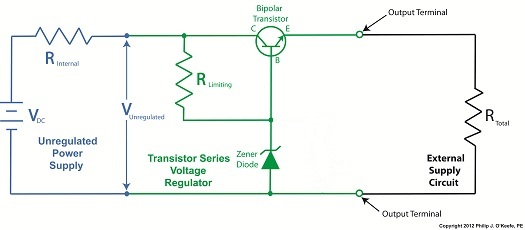
Last time we learned how the transistor opens a path for electric current to flow from the collector to the emitter in our example circuit. It does so by making use of an unregulated power supply. Now let’s see how the Zener diode fits into the mix. |

Transistors – Voltage Regulation Part XVI
Monday, November 5th, 2012
Transistors – Voltage Regulation Part XV
Sunday, October 28th, 2012

Transistors – Voltage Regulation Part XIII
Monday, October 15th, 2012|
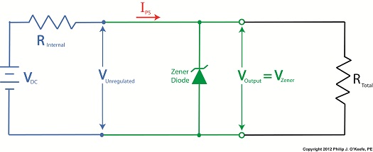
Last time we learned how the Zener diode, an excellent negotiator of current, is involved in a constant trade off, exchanging current for voltage so as to maintain a constant voltage. It draws as much current through it as is required to maintain a consistent voltage value across its leads, essentially acting as voltage regulator in order to protect sensitive electronic components from power fluctuations. Now let’s revisit our example power supply circuit and see how Ohm’s Law is used to determine the amount of electric current, IPS, that flows from the unregulated power supply and why this is important to the function of the Zener diode. See Figure 1.
Figure 1
If you’ll recall, Ohm’s Law states that current flowing through a resistor is equal to the voltage across the resistor divided by its electrical resistance. In our example that would be IPS flowing through to RLimiting. In fact, the voltage across RLimiting is the difference between the voltages at each of its ends. Applying this knowledge to our circuit, the voltage on one end is VUnregulated, while the voltage at the other is VZener. According to Ohm’s Law the equation which allows us to solve for IPS is written as: IPS = (VUnregulated – VZener) ÷ RLimiting And if we have a situation where VUnregulated equals VZener , such as when the voltage of an unregulated power supply like a battery equals the Zener voltage of a Zener diode, then the equation becomes: (VUnregulated – VZener ) = 0 And if this is true, then the following is also true: IPS = 0 ÷ RLimiting = 0 In other words, this equation tells us that if VUnregulated is equal to VZener, then the current IPS will cease to flow from the unregulated portion of the circuit towards the Zener diode and the external supply circuit. Put another way, in order for IPS to flow and the circuit to work, VUnregulated must be greater than VZener. Next week we’ll continue our discussion and see why the resistor RLimiting is necessary in order to prevent the circuit from self destructing. ____________________________________________ |

Transistors – Voltage Regulation Part XI
Monday, October 1st, 2012|
Without limits on our roadways things would get quickly out of hand. Imagine speeding down an unfamiliar highway and suddenly coming upon a sharp curve. With no speed limit sign to warn you to reduce speed, you could lose control of your car. Limits are useful in many situations, including within electronic circuits to keep them from getting damaged, as we’ll see in a moment.
Last time we introduced the Zener diode and the fact that it performs as a voltage regulator, enabling devices connected to it to have smooth, uninterrupted operation at a constant voltage. Let’s see how it works.
Figure 1
In Figure 1 we have an unregulated power supply circuit introduced in a previous article in this series. We learned that this power supply’s major shortcoming is that its output voltage, VOutput, is unregulated, in other words, it’s not constant. It varies with changes in the direct current supply voltage, VDC. It also varies with changes in, RTotal, which is the total internal resistance of components connected to it. RTotal changes when components are turned on and off by microprocessor and digital logic chips. When VOutput is not constant, those chips can malfunction, causing the device to operate erratically or not at all. But we can easily address this problem by adding a Zener diode voltage regulator between the unregulated power supply and the external supply circuit. See the green portion of Figure 2.
Figure 2
Our power supply now consists of a Zener diode and a limiting resistor, RLimiting. The limiting resistor does as its name implies, it limits the amount of electric current, IZ, flowing through the Zener diode. Without this limiting resistor, IZ could get high enough to damage the diode, resulting in system failure. Next time we’ll see how the Zener diode works in tandem with the limiting resistor to control current flow and hold the output voltage at a constant level. ____________________________________________ |


Transistors – Voltage Regulation Part VI
Sunday, August 26th, 2012| Believe it or not as a kid in grade school I used to hate math, particularly algebra. None of my teachers were able to decipher its complexities and render it comprehensible to me or the majority of my classmates. Then in high school everything changed. I had Mr. Coleman for freshman algebra, and he had a way of making it both understandable and fun, in a challenging kind of way. With 40 years of teaching under his belt, Mr. Coleman knew exactly how to convey the required information in an understandable manner, and to this day I find his insights useful in solving engineering calculations.
Last time we began our discussion on Ohm’s Law and how it may be applied to our example circuit to solve for the electrical current flowing through it. Let’s continue our discussion to see how the Law applies to only one part of the circuit. Then, we’ll use a little algebra to show how the output voltage of an unregulated power supply is affected by changes in RTotal.
Figure 1
To help us see things more clearly, in Figure 1 we’ll cover up the inside workings of the unregulated power supply side of the circuit and concentrate on the external supply part of the circuit alone. Since RTotal is connected to the terminals of the power supply, the voltage applied to RTotal is the same as the power supply output voltage, VOutput. In my previous article, we learned that according to Ohm’s Law, the current flowing through a resistance is equal to the voltage applied to it, divided by the resistance. The fact that RTotal is connected to the two output terminals like we see in Figure 1, allows us to use Ohm’s law to solve for the electrical current, I, flowing through RTotal: I = VOutput ÷ RTotal Now let’s pull the cover off of the unregulated power supply again to see what’s going on within the circuit as a whole.
Figure 2
In Figure 2 we can see that the current, I, flowing through RTotal is the same current flowing through the balance of the circuit. In the preceding blog we found that value to be: I = VDC ÷ (RInternal + RTotal) We can combine the above two equations for I to develop an algebraic relationship between VOutput and RInternal, RTotal, and VDC: VOutput ÷ RTotal = VDC ÷ (RInternal + RTotal) Then, by rearranging terms and applying the cross multiplication principle of algebra we can solve for VOutput. This involves multiplying both sides of the equation by RTotal: VOutput = RTotal × (VDC ÷ (RInternal +RTotal)) This equation tells us that although RInternal doesn’t fluctuate, VOutput will fluctuate when RTotal does. This fact is demonstrated in our equation when we make use of algebra. That is to say, when a term changes on one side of the equation, it causes the other side of the equation to change as well. In this case, when RTotal changes, it causes VOutput to change in proportion to the fixed values of VDC and RInternal. Next time we’ll look at another shortcoming of unregulated power supplies, more specifically, how one supply can’t power multiple electrical circuits comprised of different voltages. ____________________________________________ |


Transistors – Voltage Regulation Part V
Sunday, August 19th, 2012| I’m sure you’ve seen the television commercials warning about harmful interactions between prescription medications. By the same token electronic circuitry can also be adversely affected by certain combinations of electrical components, as we’ll discuss in today’s blog.
Last time we looked at a circuit schematic containing an unregulated power supply. This power supply was connected to an external supply circuit containing a number of components such as electric relays, buzzers, and lights. Each of these components has a resistance factor, and combined they have a total resistance of RTotal. We saw that when RTotal increases, the electrical current, I, decreases, and when RTotal decreases, I increases. In contrast to this increasing/decreasing activity of the total resistance RTotal, the fixed internal resistance of the unregulated power supply, RInternal, doesn’t fluctuate. Let’s explore Ohm’s Law further to see how the static effect of RInternal combines with the changing resistance present in RTotal to adversely affect the unregulated power supply output voltage, VOutput, causing it to fluctuate.
Figure 1
In Figure 1 RTotal and RInternal are operating in series, meaning they are connected together like sausage links. In this configuration their two resistances add together as if they were one larger resistor. Generally speaking, Ohm’s Law sets out that the current, I, flowing through a resistor in an electrical circuit equals the voltage, V, applied to the resistor divided by the resistance R, or: I = V ÷ R In the case of the circuit represented in Figure 1, the resistors RInternal and RTotal are connected in series within the circuit, so their resistances must be added together to arrive at a total power demand. Voltage is applied to these two resistors by the same voltage source, VDC. So, for the circuit as a whole Ohm’s Law would be written as: I = VDC ÷ (RInternal + RTotal) But, Ohm’s Law can also be applied to individual parts within the circuit, just as it can be applied to a single kitchen appliance being operated on a circuit shared with other appliances. Let’s see how this applies to our example circuit’s RTotal next week. ____________________________________________ |

Transistors – Voltage Regulation Part IV
Sunday, August 12th, 2012| We’ve all popped a circuit breaker sometime in our lives, often the result of making too heavy of an electrical demand in a single area of the house to which that circuit is dedicated. Like when you’re making dinner and operating the microwave, toaster, mixer, blender, food processor, and television simultaneously. The demand for current on a single circuit can be taxed to the max, causing it to pop the circuit breaker and requiring that trip to the electrical box to flip the switch back on.
Last time we began our discussion on unregulated power supplies and how they’re affected by power demands within their circuits. Our schematic shows there are two basic aspects to the circuit, namely, its direct current source, or VDC, and its internal resistance, RInternal. Now let’s connect the power supply output terminals to an external supply circuit through which electrical current will be provided to peripheral devices, much like all the kitchen gadgets mentioned above.
Figure 1
The external supply circuit shown in Figure 1 contains various electronic components, including electric relays, lights, and buzzers, and each of these has its own internal resistance. Combined, their total resistance is RTotal, as shown in our schematic. Current, notated as I, circulates through the power supply, through the external supply circuit, and then returns back to the power supply. The current circulates because the voltage, VDC, pushes it through the circuit like pressure from a pump causes water to flow through a pipe. RTotal and I can change, that is, increase or decrease, depending on how many components the microprocessor has turned on or off within the external supply circuit at any given time. When RTotal increases, electrical current, I, decreases. When RTotal decreases, electrical current I increases. Next time we’ll continue our discussion on Ohm’s Law, introduced last week, to show how the static effect of RInternal interacts with the changing resistance present in RTotal to adversely affect an unregulated power supply’s output voltage. ____________________________________________ |

Transistors – Voltage Regulation Part II
Sunday, July 29th, 2012| I joined the Boy Scouts of America as a high schooler, mainly so I could participate in their Explorer Scout program and learn about electronics. I will forever be grateful to the Western Electric engineers who volunteered their personal time to stay after work and help me and my fellow Scouts build electronic projects. The neatest part of the whole experience was when I built my first regulated power supply with their assistance inside their lab. But in order to appreciate the beauty of a regulated power supply we must first understand the shortcomings of an unregulated one, which we’ll begin to do here.
Last time we began to discuss how the output voltage of an unregulated power supply can vary in response to power demand, just as when sprinklers don’t have sufficient water flow to cover a section of lawn. Let’s explore this concept further.
Figure 1
Figure 1 shows a very basic representation of a microprocessor control system that operates three components, an electric relay (shown in the blue box), buzzer, and light. These three components have a certain degree of internal electrical resistance, annotated as RR, RB, and RL respectively. This is because they are made of materials with inherent imperfections which tend to resist the flow of electric current. Imperfections such as these are unavoidable in any electronic device made by humans, due to impurities within metals and irregularities in molecular structure. When the three components are activated by the microprocessor chip via field effect transistors, denoted as FET 1, 2 and 3 in the diagram, their resistances are connected to the supply circuit. In other words, RR, RB, and RL create a combined level of resistance in the supply circuit by their connectivity to it. If a single component were to be removed from the circuit, its internal resistance would also be removed, resulting in a commensurate decrease in total resistance. The greater the total resistance, the more restriction there is to current flow, denoted as I. The greater the resistance, the more I is caused to decrease. In contrast, if there is less total resistance, I increases. The result of changing current flow resistance is that it causes the unregulated power supply output voltage to change. This is all due to an interesting phenomenon known as Ohm’s Law, represented as this within engineering circles: V = I × R where, V is the voltage supplied to a circuit, I is the electrical current flowing through the circuit, and R is the total electrical resistance of the circuit. So, according to Ohm’s Law, when I and R change, then V changes. Next time we’ll apply Ohm’s Law to a simplified unregulated power supply circuit schematic. In so doing we’ll discover the mathematical explanation to the change in current flow and accompanying change in power supply output voltage we’ve been discussing. ____________________________________________ |


