| The Olympic Torch relay, soon to culminate in London, is the grand daddy of all relays, starting in one country, traversing many others, then ending its journey at the site of the Olympic Games. It passes through many athletes’ hands while on its journey, its final purpose being to light the Olympic Flame. Less glamorous, though still useful, is the relay race that often takes place within digital controls.
Last time we looked at my design solution for the control of a microprocessor controlled medical x-ray film developing machine, where a field effect transistor (FET) acted as a digital control interface between a 5 volt direct current (VDC) microprocessor and a 12 VDC buzzer. Well, controlling the buzzer wasn’t the only function of the microprocessor. It also had to control a 120 volt alternating current (VAC) drive motor, the purpose of which was to move x-ray film through a series of processes within the machine. Yet another requirement was that the machine’s drive motor run 40 minutes upon activation by a start button, then shut off. One of the challenges presented by this specification was that an FET standing alone is only suited to control direct current devices like the buzzer, but not alternating current devices like electric motors. Direct current flows in one direction only when traveling through wire, and since an FET can only pass current in one direction it is the perfect match for those applications. Now, as the name would imply, alternating current flow alternates, that is, it reverses direction and varies in intensity many times each second. This is a scenario that FETs are not equipped to handle because they can’t deal with reverse flow. This meant that, for the purpose of my developing machine, I could not use an FET to directly control the 120 VAC motor. Now let’s take a look at Figure 1 to get a basic look at how I solved the problem. |
Posts Tagged ‘electric current’

Transistors – Digital Control Interface, Part I
Monday, June 18th, 2012| In the navy, the captain is the brains behind a ship’s operations. He gathers information, makes important decisions, then issues orders. He’s not there to roll up his sleeves and swab the decks. The captain relies on the ship’s officers to act as an interface between himself and the sailors that perform the physical labor required on deck.
In this article we’ll see how the FET, that is, the field effect transistor, performs much the same role as the ship’s officers when it is used within electronic controls. There it acts as an interface between electronic components that issue commands and the electrical devices that carry them out. Last week we became familiar with field effect transistors and how their control of electrical current flow is analogous to how a faucet controls the flow of water. Although FETs can be used to vary the flow of current, they’re usually employed to perform a much simpler task, that of simply turning flow on or off, with no in-between modality. Like the captain of a ship, microprocessor and logic chips are the brains behind the operation in all sorts of industrial and consumer electronics. Figure 1 shows a few of them. Figure 1
The chips, which operate on low voltage, contain entire computer programs within them that gather information, make decisions, then instruct the higher voltage devices like motors, electrical relays, light bulbs, and audible alarms to follow. By “information,” I mean data signals received by the chip from its input connections to sensors, buttons, and other electrical components. This data informs the chip’s computer program of important operational information, like whether buttons have been pressed, switches are activated, and temperatures are normal. Based on this data, “decisions” are made by the chip using the logic contained within its program, then, depending on the decisions made, “commands” are issued by the chip. The commands, in the form of electrical output signals, are put into action by the work horses, the higher voltage devices. They, like a ship’s sailors, perform the actual physical work. There is one problem presented by this scenario, however. The electric output signals from the lower voltage chips are not suited to directly control the higher voltage devices because the signal voltage put out by the chips is too low. Even if the chip was designed to work at a higher voltage, the high level of current drawn by the motors, relays, and bulbs would lead to damage of the delicate circuitry within the chip. The chips must therefore rely on the FET to act as a digital control interface between them and the higher voltage devices, much as the ship’s captain depends on his subordinates to carry out his orders. Next week we’ll look at a real life example of how a digital interface is put into operation within an industrial product.
____________________________________________ |

Industrial Control Basics – Motor Overload Relay In Action
Sunday, March 18th, 2012|
Last week we explored the topic of thermal expansion, and we learned how the bimetal contacts in a motor overload relay distort when heated. We also discussed how the overload relay comes into play to prevent overheating in electric motor circuits. Now let’s see what happens when an overload situation occurs.
Figure 1
Figure 1 shows a motor becoming overloaded, as it draws in abnormally high amounts of electric current. Since this current also flows through the electric heater in the overload relay, the heater starts producing more heat than it would if the motor were running normally. This abnormally high heat is directed towards the bimetal switch contacts, causing them to curl up tightly until they no longer touch each other and open up. They will only close again when the overload condition is cleared up and the heater cools back down to normal operating temperature. Let’s now take a look at Figure 2 to see how the motor overload relay fits into our example of a conveyor belt motor control circuit. Once again, the path of electric current flow is denoted by red lines.
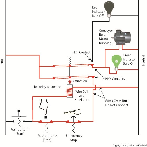
Figure 2
The circuit in Figure 2 represents what happens after Button 1 is depressed. That is, the electric relay has become latched and current flows between hot and neutral sides through one of the N.O. contacts along the path of the green indicator bulb, the motor overload relay heater, and the conveyor belt motor. The current also flows through the other N.O. contact, the Emergency Stop button, Button 2, the electric relay’s wire coil, and the motor overload relay bimetal contacts. The motor becomes overloaded, causing the overload relay heater to produce abnormally high heat. This heat is directed towards the bimetal contacts, also causing them to heat up.
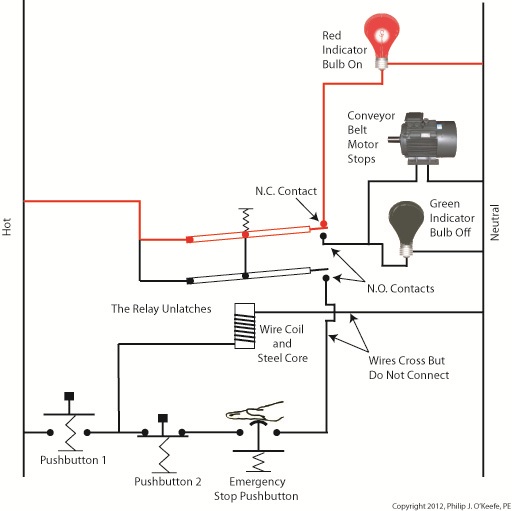
Figure 3
In Figure 3 the bimetal contacts have heated to the point that they have curled away from each other until they no longer touch. With the bimetal contacts open, electric current is unable to flow through to the electric relay’s wire coil. This in turn ends the magnetic attraction which formerly held the relay armatures against the N.O. contacts. The spring in the electric relay has pulled the armatures up, causing the N.O. contacts to open, simultaneously closing the N.C. contact. These actions have resulted in a loss of current to the green indicator bulb and electric motor. The red indicator bulb is now activated, and the conveyor motor is caused to automatically shut down to prevent damage and possible fire due to overheating. This means that even if the conveyor operator were to immediately press Button 1 in an attempt to restart the line, he would be prevented from doing so. Under these conditions the electric relay is prevented from latching, and the motor remains shut down because the bimetal contacts have been separated, preventing current from flowing through to the wire coil. The bimetal contacts will remain open until they once again cool to normal operating temperature. Once cooled, they will once again close, and the motor can be restarted. If the cause of the motor overload is not diagnosed and its ability to recur eliminated, the automatic shutdown process will repeat this cycle. Next time we’ll see how the overload relay is represented in a ladder diagram. We’ll also see how switches can be added to the circuit to allow maintenance staff to safely work. ____________________________________________
|


Industrial Control Basics – Thermal Expansion Effect on Overload Relays
Sunday, March 11th, 2012| Imagine driving on steel tires, not rubber. Don’t think it would work too well? On asphalt highways maybe not, but on the steel rails that steam locomotives travel upon, steel wheels work surprisingly well and it’s due in large part to the principles of thermal expansion and the different rates at which metal alloys expand and contract. Allow me to explain by analyzing how a locomotive“tire” is changed.
As you can imagine changing locomotive tires isn’t easy. Firstly, locomotive shop mechanics have to actually build a fire around the steel tire to heat it up. The intense heat causes its steel tire to thermally expand, meaning its steel molecules become energized by the heat and begin to vibrate. This causes the molecules to move away from each other, and this results in the tire actually growing slightly in size. This enlargement is just enough to enable mechanics to slip the tire back onto the locomotive’s wheel. Now in place, the tire is allowed to cool back down to ambient air temperatures. Cooling results in the tire’s steel molecules relaxing and moving closer to each other. The tire shrinks back to its original preheated size and tightly wraps itself around the wheel. Thermal expansion properties of metals comes into play in many other instances, including the workings of motor overload relays. Please refer to Figure 1.
Figure 1
Here overload relay components are shown in the foreground box. We see that the relay includes an electric heater and a set of two peculiar looking curved objects. These are bimetal switch contacts, so named because each is made of two, that’s the “bi” part, metal strips with different thermal properties. These strips are positioned back to back, then bonded together and curved into a shape resembling a question mark. Each of the two metals has different properties, namely, one expands at a faster rate and to a greater extent than the other when heated. This differing rate of expansion is indicative of the two metals’ diverse thermal properties. When the bimetal contact is exposed to heat, one metal strip wants to expand a lot, but it is bonded to the other metal strip which only wants to expand a little. The end result is that their point of contact distorts and changes shape. When allowed to cool back down, the metal strips contract and the contact point returns to its original shape. In our next blog we’ll see how the contact shape changes and why this shape change is important. In Figure 1 the motor is running normally and there is no overload situation. Under these conditions the motor draws electric current within the normal limits of its design. That current also flows through the heater in the overload relay causing it to generate heat, but in this situation the heat change is small enough that it doesn’t affect the bimetal switch contacts and cause them to change shape. The temperature at which the switch contacts will warp depends on the overall design of the overload relay as well as its application. Next time we’ll see what part a motor overload plays in conjunction with the overload relay’s heater and bimetal contacts. ____________________________________________
|

Industrial Control Basics – Motor Overload
Sunday, March 4th, 2012|
Last summer my wife and I did a lot of work in the garden. Many holes were dug, bags of garden soil lifted, and plants planted. It’s a new garden, and my wife has very big plans for it, so needless to say there was a lot of work to be done. On more than one occasion we would end the day moaning about our body aches and how we had overdone it. The next day we would hurt even worse, and we’d end up taking time off to recuperate. Pain is your body’s way of telling you that it needs attention, and you’d better listen to it or you may have an even heavier price to pay down the road. Electric motors can get overworked, just like our bodies. Motors are often placed into situations where they are expected to perform tasks beyond their capability. Sometimes this happens through poor planning, sometimes due to wishful thinking on the user’s part. Motors can sustain damage when stressed in this way, but they don’t have a pain system to tell them to stop. Instead, motors benefit by a specific type of electric relay known as an overload relay. But before we get into how an overload relay works, let’s get a better understanding of how overloads happen. Suppose we’re back in the telephone factory discussed in previous blogs, watching a conveyor belt move phones through the manufacturing process. An electric motor drives the conveyor belt by converting electrical energy into mechanical energy. Everything is moving along normally when all of a sudden a machine malfunctions. Telephones start piling up on a belt, and the pile up gets so bad the belt eventually gets jammed and its motor overloaded. If the electricity flow to the motor isn’t shut down promptly by means of a nearby emergency stop button or an astute operator sitting in central control, then an even bigger problem is in the making, that of a potential fire. When electricity is applied to motors they begin to operate, and their natural tendency is to want to keep operating. They do so by continuously drawing energy from the electric current being supplied to them. The greater the workload demand on the motor, the more current it requires to operate. When motors become overloaded as in the scenario presented above, they continue to draw energy unless forced to a stop. The result is an overabundance of current flowing through the motor and no outlet for its task of converting electrical energy into mechanical energy. And where is all that pent up energy to go? It becomes heat energy trapped inside the motor itself, and this heat can build up to the point where the motor becomes damaged or even bursts into flames. Next time we’ll look at how overload relays work to keep electric motors from overheating, just as our body’s pain sensors protect us from overdoing it.
____________________________________________
|

Industrial Control Basics – Latching Circuit
Sunday, January 29th, 2012| When I think of latches the first thing that comes to mind is my Uncle Jake’s outhouse and how I got stuck in it as a kid. Its door was outfitted with a rusty old latch that had a nasty habit of locking up when someone entered, and it would take a tricky set of raps and bangs to loosen. One day it was being particularly unresponsive to my repeated attempts to open it, and the scene became like something out of a horror movie. There was a lot of screaming.
When latches operate well, they’re indispensable. Let’s take our example circuit from last time a bit further by adding more components and wires. We’ll see how a latch can be applied to take the place of pressure exerted by an index finger. See Figure 1.
Figure 1
Our relay now contains an additional pivoting steel armature connected by a mechanical link to the original steel armature and spring. The relay still has one N.C. contact, but it now has two N.O. contacts. When the relay is in its normal state the spring holds both armatures away from the N.O. contacts so that no electric current will flow through them. One armature touches the N.C. contact, and this is the point at which current will flow between hot and neutral sides, lighting the red bulb. The parts of the circuit diagram with electric current flowing through them are denoted by red lines. Figure 1 reveals that there are now two pushbuttons instead of one. Now let’s go to Figure 2 to see what happens when someone presses on Button 1.
Figure 2
Again, the parts of the circuit diagram with current flowing through them are denoted by red lines. From this diagram you can see that when Button 1 is depressed, current flows through the wire coil, making it and its steel core magnetic. This electromagnet in turn attracts both steel armatures in our relay, causing them to pivot and touch their respective N.O. contacts. Electric current now flows between hot and neutral sides, lighting up the green bulb. Current no longer flows through the N.C. contact and the red bulb, making it go dark. If you look closely at Figure 2, you’ll notice that current can flow to the wire coil along two paths, either that of Button 1 or Button 2. It will also flow through both N.O. contact points, as well as the additional armature. So how is this scenario different from last week’s blog discussion? That becomes evident in Figure 3, when Button 1 is no longer depressed.
Figure 3
In Figure 3 Button 1 is not depressed, and electric current does not flow through it. The red bulb remains dark, and the green bulb lit. How can this state exist without the human intervention of a finger depressing the button? Because although one path for current flow was broken by releasing Button 1, the other path through Button 2 remains intact, allowing current to continue to flow through the wire coil. This situation exists because Button 2’s path is “latched.” Latching results in the relay’s wire coil keeping itself energized by maintaining armature contact at the N.O. contact points, even after Button 1 is released. When in the latched state, the magnetic attraction maintained by the wire coil and steel core won’t allow the armature to release from the N.O. contacts. This keeps current flowing through the wire coil and on to the green bulb. Under these conditions the relay will remain latched. But, just like my Uncle’s outhouse door, the relay can be unlatched if you know the trick to it. Relays may be latched or unlatched, and next week we’ll see how Button 2 comes into play to create an unlatched condition in which the green bulb is dark and the red bulb lit. We’ll also see how it is all represented in a ladder diagram. ____________________________________________ |


Industrial Control Basics – Electric Relay Example
Saturday, January 14th, 2012| When a starving monkey is faced with two buttons, one representing access to a banana, the other cocaine, which will he push? The cocaine, every time. The presence of buttons usually indicates a choice must be made, and electric relays illustrate this dynamic.
Last week we looked at a basic electric relay and saw how it was used to facilitate a choice in electricity flow between two paths in a circuit. Now let’s see what happens when we put a relay to use within a basic industrial control system making use of lit bulbs.
Figure 1
Figure 1 shows an electric relay that’s connected to both hot and neutral wires. At the left side is our pushbutton and the hot wire, on the right two bulbs, one lit, one not, and the neutral wire. No one is depressing the pushbutton, so an air gap exists, preventing current from flowing through the wire coil between the hot and neutral sides. With these conditions in place the relay is said to be in its “normal state.” The relaxed spring positioned on the relay armature keeps it touching the N.C. contact. This allows current to flow between hot and neutral through the armature and the N.C. contact. When these conditions exist the red bulb is lit, and this is accomplished without the need for anyone to throw a switch or press a button. In this condition the other lamp will remain disengaged and unlit. Now let’s refer to Figure 2 to see what happens when someone presses the button.
Figure 2
When the button is depressed the air gap is eliminated and the coil and wire become magnetized. They will attract the steel armature closer to them, the spring to expand, and the armature to engage with the N.O. contact. Under these conditions current will no longer flow along a path to light the red bulb because an air gap has been created between the armature and N.C. contact. The current instead flows through the N.O. contact, lighting the green bulb. It will stay lit so long as someone holds the button down. If our monkey were faced with the scenarios presented in Figures l and 2 and a banana was placed in the position of the red bulb, the cocaine in the position of the green, he might find that the regular delivery of bananas that takes place when the relay is in the N.C. contact position is enough to keep him happy. In this state he might be so full of bananas he won’t want to expend the energy to engage the button into the N.O. contact position for the delivery of cocaine. Next time we’ll revisit the subject of ladder diagrams and see how they are used to denote the paths of electric relays. ____________________________________________ |


Industrial Control Basics – Electric Relay Operation
Monday, January 9th, 2012| It’s a dark and stormy night and you’ve come to the proverbial fork in the road. The plot is about to take a twist as you’re forced to make a decision in this either/or scenario. As we’ll see in this article, an electric relay operates in much the same manner, although choices will be made in a forced mechanical environment, not a cerebral one.
When we discussed basic electric relays last week we talked about their resting in a so-called “normal state,” so designated by industrial control parlance. It’s the state in which no electric current is flowing through its wire coil, the coil being one of the major devices within a relay assembly. Using Figure 3 of my previous article as a general reference, in this normal state a relaxed spring keeps the armature touching the N.C. switch contact. While in this state, a continuous conductive path is created for electricity through to the N.C. point. It originates from the wire on the left side, which leads to the armature pivot point, travels through the armature and N.C. contact points, and finally dispenses through the wire at the right leading from the N.C. contact. Now let’s look at an alternate scenario, when current is made to flow through the coil. See Figure l, below.
Figure 1Figure 1 shows the path of electric current as it flows through the wire coil, causing the coil and the steel core to which it’s attached to become magnetized. This magnetization is strong, attracting the steel armature and pulling it towards the steel core, thus overcoming the spring’s tension and its natural tendency to rest in a tension-free state. The magnetic attraction causes the armature to rotate about the pivot point until it comes to rest against the N.O. contact, thus creating an electrical path en route to the N.O. wire, on its way to whatever device it’s meant to energize. As long as current flows through the wire coil, its electromagnetic nature will attract the armature to it and contact will be maintained with the N.O. juncture. When current is made to flow through the wire coil, an air gap is created between the armature and the N.C. contact, and this prevents the flow of electric current through the N.C. contact area. Current is forced to follow the path to the N.O. contact only, effectively cutting off any other choice or fork in the road as to electrical path that may be followed. We can see that the main task of an electric relay is to switch current between two possible paths within a circuit, thereby directing its flow to one or the other. Next time we’ll examine a simple industrial control system and see how an electric relay can be engaged with the help of a pushbutton. ____________________________________________ |

Industrial Control Basics – Introduction to Electric Relays
Tuesday, January 3rd, 2012| I’ve always considered science to be cool. Back in the 5th grade I remember fondly leafing through my science textbook, eagerly anticipating our class performing the experiments, but we never did. For some reason my teacher never took the time to demonstrate any. Undeterred, I proceeded on my own.
I remember one experiment particularly well where I took a big steel nail and coiled wire around it. When I hooked a battery up to the wires, as shown in Figure 1 below, electric current flowed from the battery through the wire coil. This set up a magnetic field in the steel nail, thereby creating an electromagnet. My electromagnet was strong enough to pick up paper clips, and I took great pleasure in repeatedly picking them up, then watching them unattach and fall quickly away when the wires were disconnected from the battery. Figure 1
Little did I know then that the electromagnet I had created was similar to an important part found within electrical relays used in many industrial control systems. An example of one of these relays is shown in Figure 2. Figure 2
So, what’s in the little plastic cube? Well, a relay is basically an electric switch, similar to the ones we’ve discussed in the past few weeks, the major difference being that it is not operated directly by human hands. Rather, it’s operated by an electromagnet. Let’s see how this works by examining a basic electrical relay, as shown in Figure 3.
Figure 3
The diagram in Figure 3 shows a basic electric relay constructed of a steel core with a wire coil wrapped around it, similar to the electromagnet I constructed in my 5th grade experiment. If the coil’s wires are not hooked up to a power source, a battery for example, no electric current will flow through it. When there is no current the coil and steel core are not magnetic. For purposes of our illustration and in accordance with industrial control parlance, this is said to be this relay’s “normal state.” Next to the steel core there is a movable steel armature, a kind of lever, which is attached to a spring. On one end of the armature is a pivot point, on the other end is a set of electrical switch contacts. When the relay is in its normal state, the spring’s tension holds the armature against the “normally closed,” or N.C., contact. If electric current is applied to the wire leading to the pivot point on the armature while in this state, it will be caused to flow on a continuous path through the armature and the N.C. contact, then out through the wire leading from the N.C. contact. In our illustration, since the armature does not touch the N.O. contact, an air gap is created that prevents electric current from traveling through the contact from the armature. Next week we’ll see how these parts come into play within a relay when electric current flows through the coil, turning it into an electromagnet. ____________________________________________ |


Industrial Control Basics – Ladder Diagrams
Sunday, December 18th, 2011| The other day I pressed the button to activate my electric garage door opener and nothing happened. I pushed again and again, still nothing. Finally, I convinced myself to get out of the car and take a closer look. A wooden board I had propped up against the side of the garage wall had come loose, wedging itself in front of the electric eye, you know, the one that acts as a safety. The board was an obstruction to the clear vision of the eye. It couldn’t see the light emitter on the other side of the door opening and wouldn’t permit the door opener to function.
The basic manual control system we looked at last week operates similarly to the eye on a garage door opener. If you can’t “close the loop,” you won’t get the power. Last week’s example was as basic as things get. Now let’s look at something a bit more complex. Words aren’t always the best vehicle to facilitate understanding, which is why I often use visual aids in my work. In the field of industrial control systems diagrams are often used to illustrate things. Whether it’s by putting pencil to paper or the flow diagram of software logic, illustrations make things easier to interpret. Diagrams such as the one in Figure l are often referred to as “ladder diagrams,” and in a minute we’ll see why.
Figure 1 Figure 1(a) shows a basic manual control system. It consists of wires that connect a power switch and electric motor to a 120 volt alternating current power source. One wire is “hot,” the other “neutral.” The hot side is ungrounded, meaning that it isn’t electrically connected to the Earth. The neutral side is grounded, that’s right, it’s driven into the ground and its energy is dissipated right into the earth, then returned back to the power grid. In Figure 1(a) we see that the power switch is open and an air gap exists. When gaps exist, we don’t have a closed electrical loop, and electricity will not flow. Figure 1(b), our ladder diagram, aka line diagram, shows an easier, more simplified representation of the manual control shown in Figure 1(a). It’s easier to decipher because there’s less going on visually for the brain to interpret. Everything has been reduced to simple lines and symbols. For example, the electric motor is represented by a symbol consisting of a circle with an “M” in it. Now, let’s turn our attention to Figure 2 below to see what happens when the power switch is closed.
Figure 2 The power switch in Figure 2(a) is closed, allowing electric current to flow between hot and neutral wires, then power switch, and finally to the motor. The current flow makes the motor come to life and the motor shaft begins to turn. The line diagram for this circuit is shown in Figure 2(b). You might have noticed that the line diagrams show in Figures 1(b) and 2(b) have a rather peculiar shape. The vertically running lines at either side depict the hot and neutral legs of the system. If you stretch your imagination a bit, they look like the legs of a ladder. Between them run the wires, power switch, and motor, and this horizontal running line represents the rung of the ladder. More complicated line diagrams can have hundreds, or even thousands of rungs, making up one humongous ladder, hence they are commonly referred to as ladder diagrams. Next week we’ll take a look at two key elements in automatic control systems, the push button and electric relay, elements which allow us to do away with the need for human intervention. ____________________________________________ |


