|
Ever been jolted with electric current? Like the time you’d just gotten out of the shower and went to plug in a lamp with damp hands? So what do you think the voltage was that caused that nasty biting feeling that resulted from your momentary lapse in good judgment? Once, while operating a subway car at a railroad museum at which I was a member, I was inadvertently “electrocuted.” I went to turn on the lights inside the car, and unbeknownst to me the light switch was faulty. When I touched it I instantly became connected to the car’s 600 volt lighting circuit. With just a split second of contact the current passed through the tip of my right index finger, along my right arm, down the right side of my body, and out the tip of my big toe, finally exiting into the metal railcar’s body. The current actually burned a hole where it had exited through my boot. The experience was both frightening and painful, but fortunately did not result in any real injury. I was lucky that the current had bypassed my heart, because if it hadn’t, I might not be alive today. That was 600 volts. Now imagine being jolted by the 4000 volts present in a microwave oven’s internal high voltage circuitry. Last week we discovered how the high voltage circuit in a microwave oven converts the ordinary, everyday 120 volts alternating current (AC) present in our homes into a much higher voltage approximating direct current (DC). This is done by an internal component known as the capacitor. The capacitor is capable of storing large amounts of electrical energy, and this can result in microwave ovens presenting a danger even when unplugged. A microwave oven capacitor is shown in Figure 1. If you happened to touch its wire terminals while it’s still charged, its power can rapidly discharge high voltage electrical current throughout your body. The electrical current from the capacitor can even stop your heart from beating, and this is exactly what caused the demise of a person featured on a soon to be released Discovery Channel program, Curious and Unusual Deaths. While being interviewed as an expert for the program, I was asked to explain this rather unique phenomenon of latent stored energy, and how it may present a threat.
Figure 1 – A Microwave Oven Capacitor Remember, a microwave oven capacitor can remain charged with dangerous electrical energy for hours, even days, after the microwave oven plug is pulled from the wall outlet. The bottom line here is that you should not attempt to fix your microwave oven, unless you are trained and certified to do so. Next week we’ll switch to a different topic, namely an electrical device known as a “wall wart.” That’s the black plastic adapter you plug into electrical outlets to power your cell phones, laptops, and other small electronics. ____________________________________________ |
Posts Tagged ‘electric current’
Electrocution by Microwave Oven
Sunday, August 21st, 2011
Wire Size and Electric Current
Sunday, March 13th, 2011| Whether or not you live or work in a city, you are probably aware of rush hour traffic and how frustrating it can be. As a matter of fact, this traffic is the number one reason many choose to live within cities providing public transportation. Instead of watching the cars pile up in front of you, you can be checking your email or reading the paper. And no matter where you live, you’ve probably encountered a narrow one-lane road at some time. If this road were to be spotted with traffic lights and double parked cars, the resulting frustration would reach a new high, one which has you craving the freedom of a crowded three-lane expressway. At least there’s the possibility of movement there.
Generally, the wider the road and the fewer the impediments, the better traffic will flow. The problems presented by vehicular traffic are analogous to those present in electrical wires. For both, obstructions are impediments to flow. You see, the thicker the metal is in a wire, the more electrical current it can carry. But before we explore why, let’s see how electric wires are classified. If you’ve ever spent any time hanging around a hardware store looking at the goodies, you’ve probably come across wire gauge numbers, used to categorize wire diameter. American Wire Gauge (AWG) is a standardized wire gauge system, used in North American industry since the latter half of the 19th Century. Handy as it is, the AWG gauge numbering system seems to go against logic, because as a wire’s diameter increases, its gauge number decreases. For example, a wire gauge number of 8 AWG has a diameter of 0.125 inches, while a gauge number of 12 AWG has a diameter of 0.081 inches. To make things easier on those who need to know this type of information, wire diameter is tabulated for each AWG gauge number and readily available in engineering reference books. So what does this have to do with electric current? To begin with, the larger the AWG number, the less current it can safely carry. If we turn to an engineering reference book, and look up information relating to an 8 AWG insulated copper wire, we find that it can safely carry an electrical current of 50 amperes, while a 12 AWG insulated copper wire can safely carry only 25 amperes. This information allows us to make important and relevant design decisions regarding a myriad of things, from electrical wiring in electronic devices, to appliances, automobiles, and buildings. So, why are bigger wires able to carry more current? Well, as you’ve heard me say before, no wire is a perfect conductor of electricity, but some metals, take copper for instance, are better conductors than others, say steel. But even the best conductors are inherently full of impurities and imperfections that resist the flow of electricity. This electrical resistance acts much like traffic lights and double parked cars that impede the flow of traffic. The larger the diameter of the wire, the less electrical resistance is present. The logic here is simple. Wire that is larger allows more paths for electrical current to flow around impurities and imperfections. The congestion present in rush hour traffic results in travel delays and hot tempers, and heat is also present in electric wires that face resistance to electricity flow. If the resistance to electric current flow is high enough, it can cause overheating. Road rage within the wires is a possibility, and if the wires get hot enough, electrical insulation can melt and burn, creating a fire. Known as the “Joule heating” effect, this phenomenon is responsible for its share of building fires. We’ll learn more about Joule heating and how wires are sized to keep electrical current flow within safe limits next week. Until then, try to keep out of traffic. _____________________________________________
|

Transformers and The Magic of Electricity
Sunday, December 5th, 2010| No, the next series of articles is not about those talking, morphing, gigantic killing machines that children love to play with. We’re going to talk about the type that adults just can’t live without.
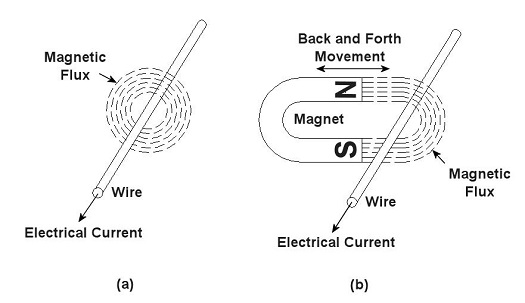
You’ve probably heard the term “electrical transformer” at some point, but you may not be entirely sure what is meant by it. Most don’t realize that they use them all the time, like when they recharge their cell phone battery. That little black box that plugs into the wall outlet is one of them, and what they do is perform the important task of reducing the 120 volts of power that fuels your home’s outlets down to a lower voltage level, for example, 12 volts, which can be used by small electronic devices. But before I explain how this reduction process works we need to understand magnets. Magnets, those wonderful curiosities that mesmerized you as a kid, keeping you busy for hours picking up nails and paper clips, have many practical applications, although they weren’t considered to be anything more than amusing novelties until the early 19th Century. That’s when a French scientist by the name of André-Marie Ampére studied the relationship between magnetism and electricity. What he found was that when an electrical current is run through a wire it turns into a magnet. Ampere’s work was then built upon by British scientist Michael Faraday. He discovered that electric current passing through wire creates magnetic lines of flux that encircle the wire as shown in Figure 1 (a). Faraday also discovered that if you move a magnet back and forth near a wire, as shown in Figure 1 (b), you can generate an electrical current in the wire.
Figure 1 – Relationships Between Electricity and Magnetism Why does this happen? Well, magnets work as they do because they have a magnetic north (N) and south (S) pole, and lines of magnetic flux extend from one pole to the other. You can actually see these lines of flux if you sprinkle iron filings between the poles. The iron filings are attracted to the magnet and align themselves along the lines as shown in Figure 2. When the lines of flux move through the wire, they induce an electrical current in it. As long as you keep the magnet moving back and forth, lines of flux will continue to pass through the wire, and the current will keep flowing. When the magnet stops moving, the current in the wire also stops.
Figure 2 – Iron Filings Aligned Along Lines of Magnetic Flux Faraday soon began experimenting with coiled wires and iron rods. He wanted to see how electrical current flowing through one coiled wire would affect another coiled wire in close proximity. His basic experimental setup is shown in Figure 3.
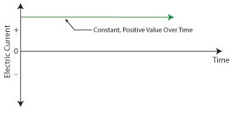
Figure 3 – Michael Faraday’s Experiment Faraday’s experiment consisted of two insulated wires, each coiled around an iron rod. The first coiled wire ran to a battery and then a switch. The switch enabled Faraday to connect and disconnect the battery to the first coil during his experiments. The second coiled wire was connected to an instrument called a Galvanometer, which measures the amount of electricity flowing through the wire. When the switch was closed, connecting the first coil to the battery, Faraday noticed that the Galvanometer’s indicator needle moved, then returned to zero. Somehow the electricity flowing from the battery to the first coil was causing an electric current to momentarily flow in the second coil. But how does electricity flow from one coil to the other if they’re not connected? It doesn’t. What’s actually taking place is known as “electromagnetic induction.” Faraday’s experiment enabled him to conclude that current flowing through the first coil set up lines of magnetic flux in the iron rod to which both coiled wires were attached. When the switch was closed, the lines of magnetic flux built in intensity until they induced a current in the second coil. But when the magnetic flux reached its full intensity, and stayed at full intensity, the current induced in the second coil stopped flowing. Faraday’s initial confusion as to the state of affairs soon changed into the Eureka! moment of discovery, and he was able to conclude that current will flow in the second coil only if the lines of magnetic flux are fluctuating in intensity. Next week we’ll see how an as yet undiscovered young inventor used the results of Faraday’s experiment to build the first electrical transformer. _____________________________________________ |


