|
Last time we examined how torque and force are created upon the driving gear within a simple gear train. Today we’ll see how they affect the driven gear.
Looking at the gear train illustration above, we see that each gear has both distance and force vectors. We’ll call the driving gear Distance vector, D1, and the driven gear Distance vector, D2. Each of these Distance vectors extend from pivot points located at the centers of their respective gear shafts. From there they extend in opposite directions until they meet at the line of action, the imaginary line which represents the geometric path along which Force vectors F1 and F2 are aligned. As we learned last time, the Force vector, F1, results from the torque that’s created at the pivot point located at the center of the driving gear. This driving gear is mounted on a shaft that’s attached to an electric motor, the ultimate powering source behind the torque. F1 follows a path along the line of action until it meets with the driven gear teeth, where it then exerts its pushing force upon them. It’s met by Force vector F2, a resisting force, which extends along the same line of action, but in a direction opposite to that of F1. These two Force vectors butt heads, pushing back against one another. F2 is essentially a negative force manifested by the dead weight of the mechanical load of the machinery components resting upon the shaft of the driving gear. Its unmoving inertia resists being put into motion. In order for the gears in the gear train to turn, F1 must be greater than F2, in other words, it must be great enough to overcome the resistance presented by F2. With the two Force vectors pushing against each other along the line of action, the angle ϴ between vectors F2 and D2, is the same as the angle ϴ between F1 and D1. Next time we’ll use the angular relationship between these four vectors to develop torque calculations for both gears in the gear train. _______________________________________ |
Posts Tagged ‘electric motor’
Distance and Force Vectors of a Simple Gear Train
Monday, May 5th, 2014
Gear Reduction Worked Backwards
Sunday, March 9th, 2014|
Last time we saw how a gear reduction does as its name implies, reduces the speed of the driven gear with respect to the driving gear within a gear train. Today we’ll see how to work the problem in reverse, so to speak, by determining how many teeth a driven gear must have within a given gear train to operate at a particular desired revolutions per minute (RPM). For our example we’ll use a gear train whose driving gear has 18 teeth. It’s mounted on an alternating current (AC) motor turning at 3600 (RPM). The equipment it’s attached to requires a speed of 1800 RPM to operate correctly. What number of teeth must the driven gear have in order to pull this off? If you’ve identified this to be a word problem, you’re correct.
Let’s first review the gear ratio formulas introduced in my previous two articles: R = nDriving ÷ nDriven (1) R = NDriven ÷ NDriving (2) Our word problem provides us with enough information so that we’re able to use Formula (1) to calculate the gear ratio required: R = nDriving ÷ nDriven = 3600 RPM ÷ 1800 RPM = 2 This equation tells us that to reduce the speed of the 3600 RPM motor to the required 1800 RPM, we need a gear train with a gear ratio of 2:1. Stated another way, for every two revolutions of the driving gear, we must have one revolution of the driven gear. Now that we know the required gear ratio, R, we can use Formula (2) to determine how many teeth the driven gear must have to turn at the required 1800 RPM: R = 2 = NDriven ÷ NDriving 2 = NDriven ÷ 18 Teeth NDriven = 2 × 18 Teeth = 36 Teeth The driven gear requires 36 teeth to allow the gear train to operate equipment properly, that is to say, enable the gear train it’s attached to provide a speed reduction of 1800 RPM, down from the 3600 RPM that is being put out from the driving gear. But gear ratio isn’t just about changing speeds of the driven gear relative to the driving gear. Next time we’ll see how it works together with the concept of torque, thus enabling small motors to do big jobs.
_______________________________________ |

Spur Gear Tooth Geometry and the Involute Curve
Sunday, January 19th, 2014|
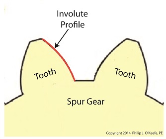
Last time we learned how spur gears mesh together to form a gear train and we examined a train consisting of just two gears, one being the driving gear, the other the driven gear. Today we’ll take a look at the geometry behind the smooth functioning of modern spur gear teeth when we identify their peculiar shape to be that of an involute curve. The curved profile of spur gear teeth conforms to a type of mathematical curve found in geometry known as an involute. The involute profile of a spur gear tooth is shown in red below. The mathematical notion of the involute was first presented in 1673 by Dutch mathematician Christiaan Huygens, in his book, Horologium Oscillatorium. Huygens’ book presents his studies on clock pendulums and the applied mathematics he used in an effort to predict their often erratic motion on ships at sea. His book ultimately dealt with far more than this, resulting in a treatise on the mathematical properties of the involutes of curves. To see how an involute curve is formed, we’ll conduct a simple experiment. One end of string is attached with a tack to a circular object, like the yellow rod shown in the following illustration. The other end of string has a red ball attached to it.
 Forming An Involute Curve If we grab the ball and pull the string taught while wrapping the string around the rod, the ball’s path will form an involute curve due to the incremental shortening of the string that occurs as it wraps around the rod. Next time we’ll see how the involute profile of gear teeth contributes to efficient mechanical energy transmission in gear trains. _______________________________________ |

Gear Trains
Monday, January 13th, 2014|
Last time we covered the basic terminology of spur gears. Today we’ll see how they interact with one another to form a gear train, such as the one depicted below.
 Meshing Spur Gears Form A Gear Train A gear train is formed when the teeth of two or more gears mesh and work together for the purpose of powering a mechanical device. A gear train can consist of as little as two gears, but trains can be so large as to contain dozens of gears, depending on the complexity of the device they are powering. But no matter how many gears are employed, there are certain key features that are shared by every gear train assembly. First, one gear within the train must be attached to a shaft rotated by a source of mechanical energy, such as an engine or electric motor. This gear is called the driving gear. The second requirement of a gear train is that at least one gear other than the driving gear is mounted to the shaft of a rotating machine part. This gear is called the driven gear.
 Locomotive Gear Train Consisting Of Two Gears The illustration above shows an exploded view of a locomotive gear train assembly consisting of two gears. The driving gear is mounted to the shaft of an electric traction motor. The driven gear is mounted to the locomotive’s axle. When a motor is attached to the axle, the two gears mesh together. The traction motor converts electrical energy into mechanical energy, which is supplied to the driving gear via the spinning motor’s shaft. The teeth of the driving gear then transmit the motor’s mechanical energy to the teeth of the driven gear, which then turn the locomotive’s wheels. It’s just one of countless operations that can be performed with gear train assemblies. Next time we’ll examine the geometry behind modern spur gear tooth design. _______________________________________ |
Transistors – Voltage Regulation Part III
Tuesday, August 7th, 2012| When my daughter was seven she found out about Ohm’s Law the hard way, although she didn’t know it. She had accidentally bumped into her electric toy train, causing its metal wheels to derail and fall askew of the metal track. This created a short circuit, causing current to flow in an undesirable direction, that is, through the derailed wheels rather than along the track to the electric motor in the locomotive as it should.
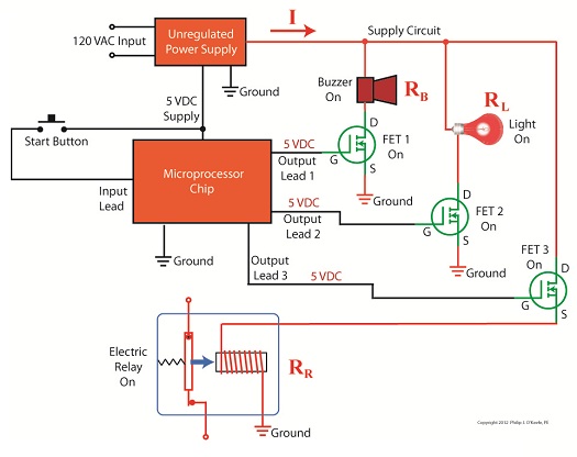
What happened during the short circuit is that the bulk of the current began to follow through the path of least resistance, that of the derailed wheels, rather than the higher resistance of the electric motor. Electric current, always opportunistic, will flow along its easiest course, in this case the short, thick metal of the wheels, rather than work its way along the many feet of thin metal wire of the motor’s electromagnetic coils. With its wheels sparking at the site of derailment the train had become an electric toaster within seconds, and the carpet beneath the track began to burn. Needless to say, mom wasn’t very happy. In this instance Ohm’s Law was at work, with a decidedly negative outcome. The Law’s basic formula concerning the toy train would be written as: I = V ÷ Rwhere, I is the current flowing through the metal track, V is the track voltage, and R is the internal resistance of the metal track and locomotive motor, or in the case of a derailment, the metal track and the derailed wheel. So, according to the formula, for a given voltage V, when the R got really small due to the derailment, I got really big. But enough about toy trains. Let’s see how Ohm’s Law applies to an unregulated power supply circuit. We’ll start with a schematic of the power supply in isolation.
Figure 1The unregulated power supply shown in Figure 1 has two basic aspects to its operation, contained within a blue dashed line. The dashed line is for the sake of clarity when we connect the power supply up to an external circuit which powers peripheral devices later on. The first aspect of the power supply is a direct current (DC) voltage source, which we’ll call VDC. It’s represented by a series of parallel lines of alternating lengths, a common representation within electrical engineering. And like all electrical components, the power supply has an internal resistance, such as discussed previously. This resistance, notated RInternal, is the second aspect of the power supply, represented by another standard symbol, that of a zigzag line. Finally, the unregulated power supply has two output terminals. These will connect to an external supply circuit through which power will be provided to peripheral devices. Next time we’ll connect to this external circuit, which for our purposes will consist of an electric relay, buzzer, and light to see how it all works in accordance with Ohm’s Law. ____________________________________________ |

Industrial Control Basics – Disconnect Switches
Sunday, March 25th, 2012| Last week our kitchen ceiling fan and light combo decided to stop working. We don’t like eating in the dark, so I was compelled to do some immediate troubleshooting. As an engineer with training in the workings of electricity I have a great respect for it. I’m well aware of potential hazards, and I took a necessary precaution before taking things apart and disconnecting wires. I made the long haul down the stairs to the basement, opened the circuit breaker in the electrical panel, and disabled the flow of electricity to the kitchen. My fears of potential electrocution having been eliminated, my only remaining fear was of tumbling off the ladder while servicing the fan.
Just as I took the precaution to disconnect the power supply before performing electrical maintenance in my home, workers in industrial settings must do the same, and a chief player in those scenarios is the motor overload relay discussed last week. It automatically shuts down electric motors when they become overheated. Let’s revisit that example now.
Figure 1
Our diagram in Figure 1 shows electric current flowing through the circuit by way of the red path. Even if this line were shut down, current would continue to flow along the path, because there is no means to disconnect the entire control system from the hot and neutral lines supplying power to it, that is, it is missing disconnect switches. Electric current will continue to pose a threat to workers were they to attempt a repair to the system. Now let’s see how we can eliminate potential hazards on the line.
Figure 2
In Figure 2 there is an obvious absence of the color red, indicating the lack of current within the system. We accomplished this with the addition of disconnect switches capable of isolating the motor control circuitry, thereby cutting off the hot and neutral lines of the electrical power supply and along with it the unencumbered flow of electricity. These switches are basically the same as those seen in earlier diagrams in our series on industrial controls, the difference here is that the two switches are tied together by an insulated mechanical link. This link causes them to open and close at the same time. The switches are opened and closed manually via a handle. When the disconnect switches are both open electricity can’t flow and nothing can operate. Under these conditions there is no risk of a worker coming along and accidentally starting the conveyor motor. To add yet another level of safety, disconnect switches are often tagged and locked once de-energized. This prevents workers from mistakenly closing them and starting the conveyor while maintenance is being performed. Brightly colored tags alert everyone that maintenance is taking place and the switches must not be closed. The lock that performs this safety function is actually a padlock. It’s inserted through a hole in the switch handle, making it impossible for anyone to flip the switch. Tags and locks are usually placed on switches by maintenance personnel before repairs begin and are removed when work is completed. Now let’s see how our example control system looks in ladder diagram format.
Figure 3
Figure 3 shows a ladder diagram that includes disconnect switches, an emergency stop button, and the motor overload relay contacts. The insulated mechanical link between the two switches is represented by a dashed line. Oddly enough, engineering convention has it that the motor overload relay heater is typically not shown in a ladder diagram, therefore it is not represented here. This wraps up our series on industrial control. Next time we’ll begin a discussion on mechanical clutches and how they’re used to transmit power from gasoline engines to tools like chainsaws and grass trimmers. ____________________________________________
|


Industrial Control Basics – Motor Overload
Sunday, March 4th, 2012|
Last summer my wife and I did a lot of work in the garden. Many holes were dug, bags of garden soil lifted, and plants planted. It’s a new garden, and my wife has very big plans for it, so needless to say there was a lot of work to be done. On more than one occasion we would end the day moaning about our body aches and how we had overdone it. The next day we would hurt even worse, and we’d end up taking time off to recuperate. Pain is your body’s way of telling you that it needs attention, and you’d better listen to it or you may have an even heavier price to pay down the road. Electric motors can get overworked, just like our bodies. Motors are often placed into situations where they are expected to perform tasks beyond their capability. Sometimes this happens through poor planning, sometimes due to wishful thinking on the user’s part. Motors can sustain damage when stressed in this way, but they don’t have a pain system to tell them to stop. Instead, motors benefit by a specific type of electric relay known as an overload relay. But before we get into how an overload relay works, let’s get a better understanding of how overloads happen. Suppose we’re back in the telephone factory discussed in previous blogs, watching a conveyor belt move phones through the manufacturing process. An electric motor drives the conveyor belt by converting electrical energy into mechanical energy. Everything is moving along normally when all of a sudden a machine malfunctions. Telephones start piling up on a belt, and the pile up gets so bad the belt eventually gets jammed and its motor overloaded. If the electricity flow to the motor isn’t shut down promptly by means of a nearby emergency stop button or an astute operator sitting in central control, then an even bigger problem is in the making, that of a potential fire. When electricity is applied to motors they begin to operate, and their natural tendency is to want to keep operating. They do so by continuously drawing energy from the electric current being supplied to them. The greater the workload demand on the motor, the more current it requires to operate. When motors become overloaded as in the scenario presented above, they continue to draw energy unless forced to a stop. The result is an overabundance of current flowing through the motor and no outlet for its task of converting electrical energy into mechanical energy. And where is all that pent up energy to go? It becomes heat energy trapped inside the motor itself, and this heat can build up to the point where the motor becomes damaged or even bursts into flames. Next time we’ll look at how overload relays work to keep electric motors from overheating, just as our body’s pain sensors protect us from overdoing it.
____________________________________________
|

Industrial Control Basics – Electric Motor Control
Sunday, February 19th, 2012| Electric motors are everywhere, from driving the conveyor belts, tools, and machines found in factories, to putting our household appliances in motion. The first electric motors appeared in the 1820s. They were little more than lab experiments and curiosities then, as their useful potential had not yet been discovered. The first commercially successful electric motors didn’t appear until the early 1870s, and they could be found driving industrial devices such as pumps, blowers, and conveyor belts.
In our last blog we learned how a latched electric relay was unlatched at the push of a button, using red and green light bulbs to illustrate the control circuit. Now let’s see in Figure 1 how that circuit can be modified to include the control of an electric motor that drives, say, a conveyor belt inside a factory.
Figure 1
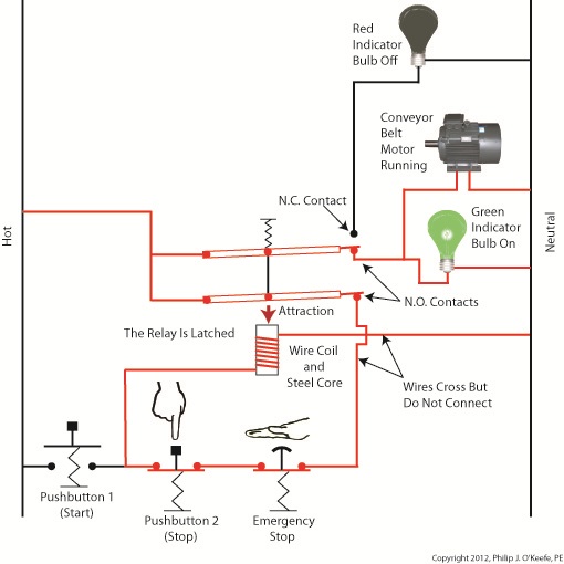
Again, red lines in the diagram indicate parts of the circuit where electrical current is flowing. The relay is in its normal state, as discussed in a previous article, so the N.O. contacts are open and the N.C. contact is closed. No electric current can flow through the conveyor motor in this state, so it isn’t operating. Our green indicator bulb also does not operate because it is part of this circuit. However current does flow through the red indicator bulb via the closed N.C. contact, causing the red bulb to light. The red and green bulbs are particularly useful as indicators of the action taking place in the electric relay circuit. They’re located in the conveyor control panel along with Buttons 1 and 2, and together they keep the conveyor belt operator informed as to what’s taking place on the line, such as, is the belt running or stopped? When the red bulb is lit the operator can tell at a glance that the conveyor is stopped. When the green bulb is lit the conveyor is running. So why not just take a look at the belt itself to see what’s happening? Sometimes that just isn’t possible. Control panels are often located in central control rooms within large factories, which makes it more efficient for operators to monitor and control all operating equipment from one place. When this is the case, the bulbs act as beacons of the activity taking place on the line. Now, let’s go to Figure 2 to see what happens when Button 1 is pushed.
Figure 2
The relay’s wire coil becomes energized, causing the relay armatures to move. The N.C. contact opens and the N.O. contacts close, making the red indicator bulb go dark, the green indicator bulb to light, and the conveyor belt motor to start. With these conditions in place the conveyor belt starts up. Now, let’s look at Figure 3 to see what happens when we release Button 1.
Figure 3
With Button 1 released the relay is said to be “latched” because current will continue to flow through the wire coil via one of the closed N.O. contacts. In this condition the red bulb remains unlit, the green bulb lit, and the conveyor motor continues to run without further human interaction. Now, let’s go to Figure 4 to see how we can stop the motor.
Figure 4
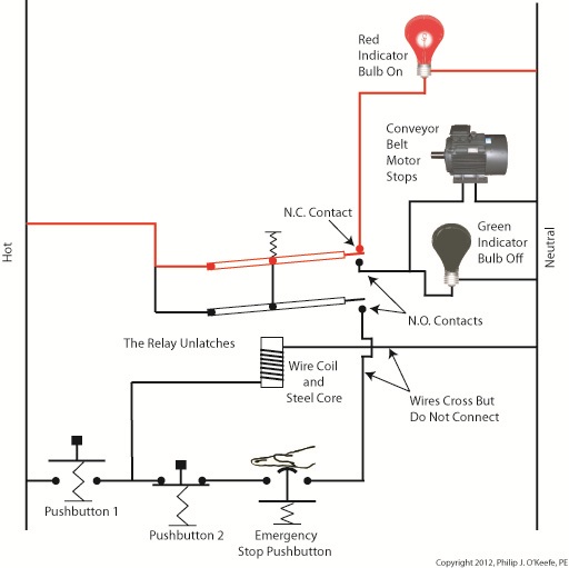
When Button 2 is depressed current flow through the relay coil interrupted. The relay is said to be unlatched and it returns to its normal state where both N.O. contacts are open. With these conditions in place the conveyor motor stops, and the green indicator bulb goes dark, while the N.C. contact closes and the red indicator bulb lights. Since the relay is unlatched and current no longer flows through its wire coil, the motor remains stopped even after releasing Button 2. At this point we have a return to the conditions first presented in Figure 1. The ladder diagram shown in Figure 5 represents this circuit.
Figure 5
Next time we’ll introduce safety elements to our circuit by introducing emergency buttons and motor overload switches. ____________________________________________ |


Industrial Control Basics – Pushbuttons
Monday, December 26th, 2011| I always enjoy watching impatient people waiting for an elevator. They press the button, and if it doesn’t come within a few seconds they press it over and over again, as if this will hurry things up. In the end they must resign themselves to the fact that the elevator will operate in its own good time.
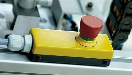
Pushbuttons, although simple in appearance like the big, red “Easy” button that’s featured in a certain business supply chain’s commercials, are actually complex behind the scenes. They perform important functions within the industrial control systems of a huge diversity of mechanized equipment. Last week we introduced ladder diagrams, used to design and document industrial control systems, and we’ll now see how they depict the action of pushbuttons within two commonly used industrial settings, the “normally open” and the “normally closed.”
Figure 1
Figure 1(a) shows a pushbutton hooked up to an electric motor. When no one is pressing it a spring in the pushbutton forces the button to rest in the up position, allowing an air gap to exist in the electrical circuit between hot and neutral and preventing current from flowing. This type of switch is characterized as a “normally open” switch in industrial control terminology. In Figure 1(b) someone depresses the button, compressing its spring and closing the air gap, which allows current to flow and the motor to operate Figure 1(c) shows the ladder diagram version of 1(a). Now let’s take a look at Figure 2 to see a different type of pushbutton, one that’s characterized as “normally closed.”
|


Industrial Control Basics – Ladder Diagrams
Sunday, December 18th, 2011| The other day I pressed the button to activate my electric garage door opener and nothing happened. I pushed again and again, still nothing. Finally, I convinced myself to get out of the car and take a closer look. A wooden board I had propped up against the side of the garage wall had come loose, wedging itself in front of the electric eye, you know, the one that acts as a safety. The board was an obstruction to the clear vision of the eye. It couldn’t see the light emitter on the other side of the door opening and wouldn’t permit the door opener to function.
The basic manual control system we looked at last week operates similarly to the eye on a garage door opener. If you can’t “close the loop,” you won’t get the power. Last week’s example was as basic as things get. Now let’s look at something a bit more complex. Words aren’t always the best vehicle to facilitate understanding, which is why I often use visual aids in my work. In the field of industrial control systems diagrams are often used to illustrate things. Whether it’s by putting pencil to paper or the flow diagram of software logic, illustrations make things easier to interpret. Diagrams such as the one in Figure l are often referred to as “ladder diagrams,” and in a minute we’ll see why.
Figure 1 Figure 1(a) shows a basic manual control system. It consists of wires that connect a power switch and electric motor to a 120 volt alternating current power source. One wire is “hot,” the other “neutral.” The hot side is ungrounded, meaning that it isn’t electrically connected to the Earth. The neutral side is grounded, that’s right, it’s driven into the ground and its energy is dissipated right into the earth, then returned back to the power grid. In Figure 1(a) we see that the power switch is open and an air gap exists. When gaps exist, we don’t have a closed electrical loop, and electricity will not flow. Figure 1(b), our ladder diagram, aka line diagram, shows an easier, more simplified representation of the manual control shown in Figure 1(a). It’s easier to decipher because there’s less going on visually for the brain to interpret. Everything has been reduced to simple lines and symbols. For example, the electric motor is represented by a symbol consisting of a circle with an “M” in it. Now, let’s turn our attention to Figure 2 below to see what happens when the power switch is closed.
Figure 2 The power switch in Figure 2(a) is closed, allowing electric current to flow between hot and neutral wires, then power switch, and finally to the motor. The current flow makes the motor come to life and the motor shaft begins to turn. The line diagram for this circuit is shown in Figure 2(b). You might have noticed that the line diagrams show in Figures 1(b) and 2(b) have a rather peculiar shape. The vertically running lines at either side depict the hot and neutral legs of the system. If you stretch your imagination a bit, they look like the legs of a ladder. Between them run the wires, power switch, and motor, and this horizontal running line represents the rung of the ladder. More complicated line diagrams can have hundreds, or even thousands of rungs, making up one humongous ladder, hence they are commonly referred to as ladder diagrams. Next week we’ll take a look at two key elements in automatic control systems, the push button and electric relay, elements which allow us to do away with the need for human intervention. ____________________________________________ |


