Posts Tagged ‘electric utility’
Wednesday, January 3rd, 2018
|
Shortly after I graduated with my engineering degree I worked as a power plant engineer at an electric utility. One day I was walking through the plant and heard a loud racket coming from the boiler feel pumps. These are the massive centrifugal pumps that deliver pressurized water to the boiler. The water is transformed into steam to drive steam turbines and spin electrical generators, which ultimately results in electrical power. The noise was so loud, it sounded like rocks were being ground up. I asked a coworker what was going on, and he replied matter-of-factly, “The pumps are cavitating.”
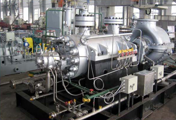
Boiler Feed Pumps Experience Cavitation
So what exactly is cavitation? We’ll find out next time when we explore the mechanics of this noisy phenomenon as it applies to boiler feed pumps and other centrifugal pumps.
opyright 2017 – Philip J. O’Keefe, PE
Engineering Expert Witness Blog
____________________________________ |
Tags: boiler, boiler feed pumps, cavitation, centrifugal pump, electric utility, electrical generator, engineering, power plant, steam turbine
Posted in Engineering and Science, Expert Witness, Forensic Engineering, Innovation and Intellectual Property, Personal Injury, power plant training, Product Liability | Comments Off on Boiler Feed Pumps Experience Cavitation
Saturday, October 24th, 2015
|
As an engineering expert with 14 years’ electric utility experience, I’ve dealt with all types of electrical power generators, including many similar to the dynamo that James Prescott Joule used in his Experiment With Electricity. Today we’ll look inside Joule’s dynamo and see how it contributed to creating electricity as well as another of Joule’s discoveries, the Joule Heating Effect.

Dynamo-Circa Early 19th Century
In Joule’s Experiment With Electricity, the dynamo was powered by a steam engine, which enabled the dynamo’s shaft to spin. As it spun, the magnet located inside the dynamo also spun, thus creating a rotating magnetic field that surrounded the dynamo’s internal copper wire coils.
The interaction between the magnetic field and wire produced electric current which flowed inside the coils. The current ultimately made its way out of the dynamo by way of external wires, to which any number of devices could be powered when attached. The net result was the engine’s mechanical energy had been converted into electrical. To learn more about the process of producing electricity with magnets see my blog on, Coal Power Plant Fundamentals – The Generator.
As electrical energy flowed through the dynamo’s wiring, some of it was converted into heat energy. This was due to resistance posed by impurities present in the makeup of the wire, impurities which served to impede the overall flow of electric current. When electrons flowing through the wire collided with these impediments, they caused heat to build up inside the wire, a phenomenon which came to be known as the Joule Heating Effect. To read more on electrical resistance and Joule heating go to my blog, Wire Size and Electric Current.
The net result of Joule’s Experiment With Electricity was to further prove the link between chemical, heat, mechanical and electrical energies as set out in the Law of Conservation of Energy. And I suspect that knowledge was later put to use by Joule’s family for the betterment of their brewery business.
Next time we’ll use Joule’s experimental findings in conjunction with de Coriolis’ Kinetic Energy Formula to quantify the energy of the falling coffee mug we’ve been watching.
Copyright 2015 – Philip J. O’Keefe, PE
Engineering Expert Witness Blog
____________________________________ |
Tags: de Coriolis, dynamo, electric utility, electrical energy, electrical power generators, electrical resistance, engineering expert, heat energy, James Prescott Joule, Joule heating, Joule's experiment with electricity, law of conservation of energy, power plant, wire size and electric current
Posted in Engineering and Science, Expert Witness, Forensic Engineering, Innovation and Intellectual Property, Personal Injury, power plant training, Product Liability | Comments Off on Joule’s Dynamo – The Joule Heating Effect
Sunday, June 24th, 2012
| Not too long ago I was retained as an engineering expert to testify on behalf of a plaintiff who owned a sports bar. The place was filled with flat screen televisions that were plugged into 120 volt alternating current (VAC) wall outlets. To make a long story short, the electric utility wires that fed power to the bar were hit by a passing vehicle, causing the voltage in the outlets to increase well beyond what the electronics in the televisions could handle. The delicate electronics were not suited to be connected with the high voltage that suddenly surged through them as a result of the hit, and they overloaded and failed.
Similarly, lower voltage microprocessor and digital logic chips are also not suited to directly connect with higher voltage devices like motors, electrical relays, and light bulbs. An interface between the two is needed to keep the delicate electronic circuits in the chips from overloading and failing like the ill fated televisions in my client’s sports bar. Let’s look now at how a field effect transistor (FET) acts as the interface between low and high voltages when put into operation within an industrial product.
I was once asked to design an industrial product, a machine which developed medical x-ray films, utilizing a microprocessor chip to automate its operation. The design requirements stated that the product be powered by a 120 VAC, such as that available through the nearest wall outlet. In terms of functionality, upon startup the microprocessor chip was to be programmed to first perform a 40-minute warmup of the machine, then activate a 12 volt direct current (VDC) buzzer for two seconds, signaling that it was ready for use. This sequence was to be initiated by a human operator depressing an activation button.
The problem presented by this scenario was that the microprocessor chip manufacturer designed it to operate on a mere 5 VDC. In additional, it was equipped with a digital output lead that was limited in functionality to either “on” or “off” and capable of only supplying either extreme of 0 VDC or 5 VDC, not the 12 VDC required by the buzzer.
Figure 1 illustrates my solution to this voltage problem, although the diagram shown presents a highly simplified version of the end solution.

Figure 1
The illustration shows the initial power supplied at the upper left to be 120 VAC. This then is converted down to 5 VDC and 12 VDC respectively by a power supply circuit. The 5 VDC powers the microprocessor chip and the 12 VDC powers the buzzer. The conversion from high 120 VAC voltage to low 5 and 12 VDC voltage is accomplished through the use of a transformer, a diode bridge, and special transistors that regulate voltage. Since this article is about FETs, we’ll discuss transistor power supplies in more depth in a future article.
To make things a little easier to follow, the diagram in Figure 1 shows the microprocessor chip with only one input lead and one output lead. In actuality a microprocessor chip can have dozens of input and output leads, as was the case in my solution. The input leads collect information from sensors, switches, and other electrical components for processing and decision making by the computer program contained within the chip. Output leads then send out commands in the form of digital signals that are either 0 VDC or 5 VDC. In other words, off or on. The net result is that these signals are turned off or on by the program’s decision making process.
Figure 1 shows the input lead is connected to a pushbutton activated by a human. The output lead is connected to the gate (G) of the FET. The FET is shown in symbolic form in green. The FET drain (D) lead is connected to the buzzer and its source (S) lead terminates in connection to electrical ground to complete the electrical circuit. Remember, electric current naturally likes to flow from the supply source to electrical ground within circuits, and our scenario is no exception.
Next time we’ll see what happens when someone presses the button to put everything into action.
____________________________________________
|
Tags: 12 VDC, 120VAC, 5 VDC, alternating current, digital control, digital control interface, digital interface, digital logic chips, diode bridge, direct current, drain, electric ground, electric relays, electric utility, electrical circuit, electronic devices, engineering expert witness, FET, field effect transistor, forensic engineer, gate, high voltage, industrial product, input signal, light bulbs, low voltage, microprocessor control, motors, output signal, overloaded, power supply, pushbutton, source, surge, television, transformer, transistors, voltage regulator, x-ray film machine
Posted in Engineering and Science, Expert Witness, Forensic Engineering, Innovation and Intellectual Property, Personal Injury, Product Liability, Professional Malpractice | Comments Off on Transistors – Digital Control Interface, Part II
Sunday, December 18th, 2011
| The other day I pressed the button to activate my electric garage door opener and nothing happened. I pushed again and again, still nothing. Finally, I convinced myself to get out of the car and take a closer look. A wooden board I had propped up against the side of the garage wall had come loose, wedging itself in front of the electric eye, you know, the one that acts as a safety. The board was an obstruction to the clear vision of the eye. It couldn’t see the light emitter on the other side of the door opening and wouldn’t permit the door opener to function.
The basic manual control system we looked at last week operates similarly to the eye on a garage door opener. If you can’t “close the loop,” you won’t get the power. Last week’s example was as basic as things get. Now let’s look at something a bit more complex.
Words aren’t always the best vehicle to facilitate understanding, which is why I often use visual aids in my work. In the field of industrial control systems diagrams are often used to illustrate things. Whether it’s by putting pencil to paper or the flow diagram of software logic, illustrations make things easier to interpret. Diagrams such as the one in Figure l are often referred to as “ladder diagrams,” and in a minute we’ll see why.

Figure 1
Figure 1(a) shows a basic manual control system. It consists of wires that connect a power switch and electric motor to a 120 volt alternating current power source. One wire is “hot,” the other “neutral.” The hot side is ungrounded, meaning that it isn’t electrically connected to the Earth. The neutral side is grounded, that’s right, it’s driven into the ground and its energy is dissipated right into the earth, then returned back to the power grid. In Figure 1(a) we see that the power switch is open and an air gap exists. When gaps exist, we don’t have a closed electrical loop, and electricity will not flow.
Figure 1(b), our ladder diagram, aka line diagram, shows an easier, more simplified representation of the manual control shown in Figure 1(a). It’s easier to decipher because there’s less going on visually for the brain to interpret. Everything has been reduced to simple lines and symbols. For example, the electric motor is represented by a symbol consisting of a circle with an “M” in it.
Now, let’s turn our attention to Figure 2 below to see what happens when the power switch is closed.

Figure 2
The power switch in Figure 2(a) is closed, allowing electric current to flow between hot and neutral wires, then power switch, and finally to the motor. The current flow makes the motor come to life and the motor shaft begins to turn. The line diagram for this circuit is shown in Figure 2(b).
You might have noticed that the line diagrams show in Figures 1(b) and 2(b) have a rather peculiar shape. The vertically running lines at either side depict the hot and neutral legs of the system. If you stretch your imagination a bit, they look like the legs of a ladder. Between them run the wires, power switch, and motor, and this horizontal running line represents the rung of the ladder. More complicated line diagrams can have hundreds, or even thousands of rungs, making up one humongous ladder, hence they are commonly referred to as ladder diagrams.
Next week we’ll take a look at two key elements in automatic control systems, the push button and electric relay, elements which allow us to do away with the need for human intervention.
____________________________________________ |
Tags: automatic control, electric circuit, electric current, electric motor, electric relay, electric utility, engineering expert witenss, forensic engineer, ground, hot, industrial control, ladder diagram, ladder logic, line diagram, manual control, motor control, neutral, power flow, power grid, power switch, push button, visual aid, wires
Posted in Courtroom Visual Aids, Engineering and Science, Expert Witness, Forensic Engineering, Innovation and Intellectual Property, Personal Injury, Product Liability, Professional Malpractice | Comments Off on Industrial Control Basics – Ladder Diagrams
Sunday, September 18th, 2011
| Some people just have a knack in the kitchen, and my wife is among them. She transforms raw ingredients into the most amazing culinary delights, almost like she’s waving a magic wand. The finished products are works of art, hand crafted with tender loving care, and lucky me, I get to feast on them regularly!
During the course of my engineering career I’ve been employed within many industries, and at one point I made the decision to leave the electric utility industry and enter into the world of food manufacturing. I accepted the position of Plant Engineer with a wholesale manufacturer of baking ingredients and frozen pastry products. My main responsibility was the design of food manufacturing equipment and their production lines.
What I had expected to be a relatively straightforward process soon proved to be more challenging. I was no longer working with hard metal as my raw material, that is, gears, nuts, and bolts, but a whole new arena of things described by adjectives such as gooey and pastey. Engineers don’t typically create food products, and let’s face it, you probably wouldn’t want to eat anything that I cooked anyway! But an engineer working within a food manufacturing plant must act as a liaison between the worlds of engineering design and the culinary arts.
Now food manufacturers typically hire professional chefs to develop new products in their research and development (R&D) kitchens. Like my wife, they’re well qualified to produce wonderful hand-made culinary delights. The sticky part comes in when their small batch recipes and preparation techniques don’t translate smoothly to the world of mass production. When it comes to handling food, human fingers are far superior to metal machinery, and raw ingredients behave differently for each.
Herein lies much of the challenge for design engineers within the food industry. How do you design equipment and production lines to make huge quantities of food that look and taste as good as the prototype products made by hand in the R&D kitchen? Next week we’ll find out.
____________________________________________

|
Tags: bolts, electric utility, engineering expert witness, food manufacturing, food manufacturing equipment design, food manufacturing plant, food processing equipment, forensic engineer, gears, machine design, machinery, nuts, plant engineer, production line, research and development
Posted in Engineering and Science, Expert Witness, Forensic Engineering, Innovation and Intellectual Property, Personal Injury, Product Liability | Comments Off on Food Manufacturing Challenges
Sunday, January 2nd, 2011
| Each day millions of Americans start their mornings with coffee, brewed in a coffee maker, and a microwaved breakfast. They flick on the light and exhaust fan before starting their showers and blow dry their hair afterwards. Each of these acts of modern living is a small miracle. And if you’re like most people you can’t see the power plant supplying the power to your modern conveniences from your home, and how the electricity travels from the plant to you isn’t too clear.
Truth is the process of supplying our homes with power isn’t as straightforward as you might think, and the actual transmission of that power isn’t straightforward at all. To begin with, the wires used in power lines are less than perfect conductors of electricity. Along any given length of wire there are all sorts of imperfections in the metal, and these tend to resist the flow of electrical current. These imperfections will always exist to some extent, even with the best manufacturing techniques and quality control, and the longer the power line, the more resistance the power flow will meet. The result is loss of electrical power. If there weren’t some kind of compensatory action at work to rectify this, your morning routine wouldn’t be nearly so smooth.
To address the problem of power loss electric utilities use step-up transformers, similar to the one in Figure 1. This enables voltage produced by the generator at the plant to be raised to a higher voltage, in turn enabling it to travel longer distances and remain effective.

Figure 1 – Electricity Leaving the Power Plant Goes Through a Step-Up Transformer
For example, let’s say that an electric generator puts out 12,000 volts, and a step-up transformer raises that to 765,000 volts, enabling transmission to customers far away. If you will recall from last week’s blog, with electrical transformers, there is an inverse relationship between voltage and current. So, when a step-up transformer increases input voltage, it actually results in a lowering of electrical current. So how does this phenomenon aid in power transmission? Simply put, when there is less current flowing through the wires, there is an accompanying reduction in power loss over the long length of the transmission line.
Let’s take a look at what happens when the power reaches our homes. Figure 2 shows a simplified distribution route from the power plant.

Figure 2 – A Step-Down Transformer is Used to Supply Electric Utility Customers
First, the higher voltage originating from the step-up transformer at the power plant is decreased by the use of a step-down transformer located in a substation many miles away at the other end of the transmission line. The use of this intermediary step-down transformer effectively lowers the voltage and at the same time raises the current at the other end of the line, the end where customers like you and I are waiting to use our hair dryers unimpeded. The path that the power follows is somewhat circuitous, but well planned out, with numerous strategically positioned distribution lines acting as the final leg of delivery. These distribution lines do what their name implies, they weave their way along streets and alleys, finally distributing electricity to customers.
A step-down transformer located in a substation along the power transmission route allows this all to happen. It can readily convert the 765,000 volts being sent by the power plant to the 25,000 volts needed to feed distribution power lines. These, in turn, power individual homes, hospitals, etc. Now you obviously can’t plug a television into a 25,000 volt wall outlet located in your house, so another step-down transformer is required to temper it into power that’s both usable and safe. The one in our diagram is mounted on a nearby utility pole, and its job is to lower the 25,000 volts which it receives into a more manageable 240 and 120 volts, which is then fed into your home.
That wraps up our series on electrical transformers. Perhaps the next time you flip that switch in your home, whether it be on your hair dryer, TV, or what have you, you’ll pause for a moment to reflect on the long path it has followed to make your life just a little bit easier.
_____________________________________________

|
Tags: current, distribution line, electric utility, electrical safety, electrical transformer, engineering expert witness, forensic engineer, high voltage, low voltage, power loss, power plant, resistance, step down transformer, step up transformer, transmission line, utility pole, voltage
Posted in Engineering and Science, Personal Injury, Product Liability | Comments Off on Transformers – Electric Utility Power Savers
Sunday, December 26th, 2010
|
As a child I considered the reindeer Rudolph, with his nose so bright, to be a marvel of engineering. Now an adult, I remain perplexed as to the mystery behind the self-generating power source behind his nose. Did it ever overheat? I wondered. Perhaps today’s discussion can shed some light on the matter.
During the course of our discussion of electricity certain terms have been tossed about, like voltage and current. For some the distinction between the two may be unclear, and that is what we’ll be addressing today.
Electricity is a rather abstract phenomenon, but you may consider the flow of electrical current through a wire to be much like water flowing through a garden hose. The water won’t flow unless there’s sufficient pressure behind it, and that pressure is supplied by pumps, either at your city water works or your personal well. Take away the pressure, and the water stops flowing through the hose.
Electricity flows in much the same manner. It requires a pushing pressure to get it on its journey from power plant to home, and that pressure is voltage. Take away voltage, and the current stops flowing through the wire. Voltage is, of course, produced by an electrical generator at the power plant.
Last time we saw how an electrical transformer can reduce high voltage to low voltage and how this process also works in reverse. But how can that be? How can low voltage be turned into high? Is it really possible to get “something from nothing”? Let’s take a closer look.
When a light bulb burns out in your home, you routinely look at the bulb to see how many watts it is so you can replace it with the same type. But what exactly is a “watt”? It’s a unit of power, and the markings on the bulb tell you how much electrical power it consumes when you use it. Generally speaking, this electrical power is related to voltage and current by this formula:
Power = Volts × Electrical Current
Knowing this, if I have a 60 watt bulb in a table lamp, and I plug it into a 120 volt wall outlet, then how much electrical current is the lamp going to draw from the outlet? Using the formula above and a little algebra, we get:
Electrical Current = Power ÷ Volts
Electrical Current = 60 watts ÷ 120 volts = 0.5 amperes
And believe it or not, this same formula that’s used to assess power of a light bulb also applies to electrical transformers. Basically, the power going into the transformer is equal to the power coming out.
To see how this works, consider the example step-up transformer shown in Figure 1, which converts a low voltage to a higher one. By the way, “step up” transformers have all sorts of applications. For example, they are used by electric utilities to raise the voltage produced by a power plant to make it more economical to transmit to far away customers. We’ll get into that in another article.

Figure 1 – A Step-Up Transformer
In this example the input voltage on the primary coil is stepped up from 120 volts to 480 volts on the secondary coil, and this works according to the formula we learned about in last week’s blog:
NP ÷ NS = VP ÷ VS
where NP and NS are the number of turns of wire in the primary and secondary coils respectively, and VP and VS are the voltages of the primary and secondary coils respectively. Plugging in the numbers we get:
50 turns ÷ 200 turns = 120 volts ÷ VS
[(200 turns ÷ 50 turns) × 120 volts] = VS = 480 volts
Okay, for the sake of our example let’s say that an electric motor is connected to the 480 volt secondary coil. We have an electric meter hooked up to the primary coil and we measure a 2 ampere (a.k.a. “amps”) electrical current flowing through it. Without having the benefit of another electric meter positioned at the secondary coil, how can we measure how much electrical current is flowing through it? The current flowing through the secondary coil is found by equalizing the power in the primary and secondary coils:
PowerP = PowerS
Another way of stating this is to say that electrical power is equal to volts times current, so the equation becomes:
VP × IP = VS × IS
where IP and IS are the primary coil and secondary coil currents, respectively. Plugging in the numbers and working a little algebra we get the electrical current in the secondary coil:
120 volts × 2 amps = 480 volts × IS
IS = (120 volts × 2 amps) ÷ 480 volts = 0.5 amps
This shows us that the current flowing in the secondary coil is lower than that of the primary coil. It is therefore obvious that the voltage increase in the secondary coil comes at the expense of electrical current that can flow through the secondary coil. Squeeze down on current, voltage goes up. Squeeze down on voltage, current goes up. The power flowing through the transformer stays the same.
Conversely, step-down transformers reduce the voltage coming in, and thereby produce the reverse effect. There is an actual increase in current that can flow through the secondary coil. This principle exemplifies the tradeoff process which is often present in science and engineering.
Next time we’ll explore how both step-up and step-down transformers are used by electric utilities to transmit power from power plants to its customers tied into the utility grid. As for Rudolph and his power source, that’s still under investigation.
_____________________________________________

|
Tags: amperes, amps, current, electric utility, electrical generator, electrical transformer, engineering expert witness, forensic engineer, power, power plant, primary coil, secondary coil, step down transformer, step up transformer, transformer core, voltage, volts, watts
Posted in Engineering and Science, Personal Injury, Product Liability | Comments Off on Transformers – The Voltage/Current Trade-Off
Sunday, December 19th, 2010
| Aside from the magical manifestation of innumerable top hats and replicate bodies that the movie The Prestige boasts is possible, there are many other fascinating applications of electricity, as we’ll see today.
Last time we learned how George Westinghouse’s chief engineer, William Stanley, developed the first practical transformer for electric utility use. Now let’s see how it works, as illustrated in Figure 1.

Figure 1 – The Basic Electrical Transformer
What we have here is an alternating current (AC) power source. And much like an electrical generator in a utility power plant, it is connected via power lines to the primary coil wires of a transformer, such as the one which feeds power to your house. The voltage applied by the source, that is, the power plant, to the primary coil is known as VP, and the electrical current flowing through the primary coil is referred to as IP.
As we learned last week, the continually varying electrical current flowing through the coil creates lines of magnetic flux, which also continually vary. In our diagram the lines of flux flow around the core of the transformer. The magnetic flux present in the core then induces AC voltage, or VS, and current, or IS, to the secondary coil when its wires are connected to something requiring an electrical load to operate. Some examples would be light bulbs, TV’s, and most appliances found in the average home.
As was mentioned last week, the number of wire turns, or loops, in the secondary coil as compared to the primary coil determine how the transformer will change the voltage that is applied to it. An example of this phenomenon can be observed in the power lines supplying electricity to our homes. Voltage from power plants is too high to be introduced into our homes, so transformers convert it to a lower voltage, one which can be used by the myriad of electrical devices we couldn’t live without.
To get an idea of how this voltage changing works, let’s consider Figure 2.

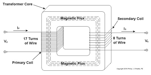
Figure 2 – Basic Transformer Example
We can see that the primary coil has 17 turns of wire and the secondary coil has 8. For purposes of our example and to keep the numbers workable, let’s arbitrarily say that VP = 5 volts AC. By the way, the power initially coming into the transformer feeding your home is typically measured in the thousands of volts.
Now it’s time to do some math. Based on this input voltage and the number of wire turns in each coil, what would the voltage be on the secondary coil? As William Stanley discovered, it’s a matter of ratios and algebra, and it works according to this formula:
NP ÷ NS = VP ÷ VS
Here NP and NS are the number of turns of wire in the primary and secondary coils, respectively. So plugging in the numbers we get:
17 turns ÷ 8 turns = 5 volts ÷ VS
[(8 turns ÷ 17 turns) x 5 volts] = VS = 2.3 volts
This tells us that the transformer in our example reduces, or “steps down” 5 volts AC to just under half the voltage. So the transformer changed a higher voltage to a lower voltage. By the same token, a large utility transformer can be used to reduce transmission line voltage to one which can be used safely within our homes.
Like magic, this mechanism also works in reverse. For example, you can apply 2.3volts AC to the 8 turn coil and you will get 5 volts AC out of the 17 turn coil, resulting in a “stepping up” of voltage.
But wait a minute. How can you possibly get more voltage out than you put in? Next time we’ll find out.
_____________________________________________

|
Tags: AC, alternating current, distribution transformer, electric utility, engineering expert witness, forensic engineer, generator, George Westinghouse, iron core, magnetic flux, power lines, primary coil, secondary coil, step down transformer, step up transformer, transformer, voltage change, William Stanley
Posted in Engineering and Science, Personal Injury, Product Liability | Comments Off on Transformers – Something To Do With The Flux
Sunday, December 12th, 2010
| If you’ve seen the movie The Prestige, you know just how “tricky” electricity can be, and if you haven’t seen it yet, you’ve yet to see a great movie. In it, Hugh Jackman uses the magical properties of electricity to pull off a magic trick the likes of which the world has never seen. But that’s all I’ll say about that… see the movie.
In 1886, a young American inventor named William Stanley did some serious thinking about Michael Faraday, the British scientist we introduced last week, and his work with electricity and magnetism. Stanley figured out how to put it all together. The result was the world’s first electrical transformer.
What fueled Stanley’s curiosity? Like most good inventors, he perceived a need and sought to fill it. At the time George Westinghouse was developing his alternating current (AC) electric utility power system, the same basic system we use today. As Westinghouse’s chief engineer, Stanley was given the task of figuring out a way to efficiently change voltage levels on an AC power grid. The industrial revolution was in full swing, and for various industrial purposes factories needed to operate on voltage levels different from those produced by the Westinghouse generators.
Stanley approached the task before him with the benefit of knowledge supplied by Faraday’s experimentation. He knew that Faraday was able to cause current to flow through a wire by moving a magnet near it back and forth. This phenomenon occurred because lines of magnetic flux were varying over time with respect to the wire through the magnet’s movement. Being aware of the vicissitudes of alternating current, the way it varies in intensity and direction, Stanley was able to conclude that any lines of magnetic flux generated by AC current flowing through a coiled wire would also tend to vary over time. Armed with this knowledge, Stanley replaced the DC battery used in Faraday’s experiment with an AC generator. This modified setup is shown in Figure 1.

Figure 1 – Faraday’s Experiment Modified With An AC Power Source
In the modified setup the switch is closed, causing the AC power flowing through the first coiled wire to create lines of magnetic flux in the iron rod. These lines of flux continually vary and thus induce AC flow in the second coil. The action taking place is duly recorded by a Galvanometer needle, which keeps moving so long as the switch remains closed.
Stanley also knew that the voltage created in the second coiled wire was dependent on how many turns, or loops, of wire were present in it compared to the number of turns of wire in the first coil. He made the observation that if less turns were present in the second coiled wire as compared to the first, less voltage would also be emitted from the second coiled wire. This demonstrates the phenomenon of changing voltage with respect to supply delivered by the AC generator to the first coil.
Putting these findings together, Stanley was able to develop the first practical electrical transformer, whose basic design is shown in Figure 2. Here we see that the iron rod from Faraday’s experiment has been replaced with an iron transformer core resembling a squared off doughnut.

Figure 2 – A Basic Electrical Transformer
Next time we’ll get into the math behind this discussion, and we’ll see how Stanley’s transformer worked.
_____________________________________________
|
Tags: AC, alternating current, battery, DC, direct current, electric utility, electromagnetism, engineering expert witness, Faraday's experiment, forensic engineer, generator, George Westinghouse, inductor, magnetic flux, power grid, primary coil, secondary coil, transformer, transformer design, William Stanley, wire coil
Posted in Engineering and Science, Innovation and Intellectual Property, Personal Injury, Product Liability | Comments Off on Transformers – Alternating Current Does the Trick
Sunday, July 18th, 2010
Did you know that even a perpetual motion machine will eventually come to a stop due to uncontrollable factors?
Well, uncontrollable factors are at play in power plants, too. If you recall from our last article, heat rate is industry jargon for gauging how efficiently a coal-fired power plant is operating. We learned that heat rate can be affected by things like missing thermal insulation on pipes and equipment. Missing insulation is, of course, a thing that is under human control and easily corrected, but there are some things that affect heat rate that we just can’t do anything about. They’re called, appropriately enough, uncontrollable factors.
Uncontrollable factors exist because anything devised and made by fallible humans who are beholden to the myriad laws of the universe cannot be 100 percent efficient. At their best utility coal fired power plants have an overall efficiency of between 30 and 40 percent. That means 60 to 70 percent of the energy available in the coal gets lost in the process of generating electricity. A terrible waste, right? And yet there’s nothing we can do to trim these losses until improvements in the present level of technology take place. Just as our ability to track microbes is dictated by the strength and accuracy of our magnifying equipment, so are we hampered by the tools we have at our disposal to deal with inefficiencies such as energy losses.
So where does this energy get lost due to uncontrollable factors? The first and probably most obvious place to look is the smoke stack. Energy is also lost in three other ways: friction between equipment parts, auxiliary power consumption, and in a piece of equipment known as a condenser. Let’s look at each.
In the most basic of terms, when coal is introduced into a power plant boiler it is combined with air and burned. This burning process releases heat energy, but it also forms gases that contain nitrogen and compounds like carbon monoxide and carbon dioxide. There’s also some water vapor formed by moisture in the coal and air. These gases and vapor absorb some of the heat energy released. To keep the combustion process going the gases and vapor must be removed from the boiler by powerful fans and sent up the smoke stack. Now, boilers are designed to absorb much of the heat energy from the gases and vapor that make their way to the stack, but they cannot possibly absorb it all. The result is that a significant amount of heat escapes up the smoke stack into the atmosphere along with the gases.
Friction between parts is present everywhere in a power plant. It exists in the bearings on the shafts of motors, pumps, and steam turbines, slowing them down and hindering their operating capacity. Friction also exists where moving water and steam are present, impeding their ability to flow through piping systems. There is even friction working against the steam as it flows through parts in the turbine. Extra energy has to be expended to overcome this friction. This is energy that could be used to generate electricity.
Now at some point in your life you’ve probably heard it said, “You need money to make money,” and this is very true. It takes a certain investment of resources to produce a profit-making enterprise. This investment principle holds true for the making of electricity, too. The bottom line is you need electricity to make electricity. Specifically, you have to use significant amounts of electricity to power machinery that is essential to move coal, air, combustion gases, and water through the process of making electricity in the power plant. This is called auxiliary power. It’s the electricity siphoned off by the various pieces of equipment in a power plant in its quest to generate electrical energy to be sold to customers.
Another major factor at play in uncontrollable energy losses is in a piece of equipment integral to the very function of power plants: the condenser. It comes into play when water is boiled to make steam which then travels through the turbine, spinning its electrical generator and creating electric power. Unfortunately even the most efficient of steam turbines cannot use 100% of the heat energy coming at it from the steam.
You see, after steam leaves the turbine, it’s turned back into water by a condenser so it can be sent back to the boiler to be turned into steam again. One of the reasons that this is done is so that the boiler does not have to be continuously filled with fresh, purified water. Water purification is necessary to keep minerals, seaweed, fish scales, and other nasty things from clogging up and damaging the boiler and steam turbine, and purified water is not as readily available as, say, lake water. The condenser acts as a heat exchanger that is hooked up to the steam turbine exhaust. It has tubes inside of it in which cold water flows, water which is drawn in from a nearby body of water, most often a river or lake. As steam blows across the outside of the cold water tubes in the condenser, it gives up its remaining heat energy and condenses into water again, then it is returned to the boiler to repeat its journey. The river water within the tubes of the condenser flows back into the river, carrying with it the heat energy removed from the steam.
That wraps up our discussion about coal power plant efficiency. Next time we’ll discuss a new topic: coal fired power plant furnace explosions.
_____________________________________________
|
Tags: auxiliary power, boiler, coal power plant efficiency, condenser, electric utility, electrical generator, electricity, engineering expert witness, forensic engineer, friction, heat energy, heat rate, smoke stack, steam turbine
Posted in Engineering and Science | Comments Off on Coal Power Plants, Far From Perfect


