Posts Tagged ‘electrical energy’
Wednesday, May 25th, 2016
|
My activities as an engineering expert often involve creative problem solving of the sort we did in last week’s blog when we explored the interplay between work and kinetic energy. We used the Work-Energy Theorem to mathematically relate the kinetic energy in a piece of ceramic to the work performed by the friction that’s produced when it skids across a concrete floor. A new formula was derived which enables us to calculate the kinetic energy contained within the piece at the start of its slide by means of the work of friction. We’ll crunch numbers today to determine that quantity.
The formula we derived last time and that we’ll be working with today is,
 Calculating Kinetic Energy By Means of the Work of Friction
where, KE is the ceramic piece’s kinetic energy, FF is the frictional force opposing its movement across the floor, and d is the distance it travels before friction between it and the less than glass-smooth floor brings it to a stop.
The numbers we’ll need to work the equation have been derived in previous blogs. We calculated the frictional force, FF, acting against a ceramic piece weighing 0.09 kilograms to be 0.35 kilogram-meters/second2 and the measured distance, d, it travels across the floor to be equal to 2 meters. Plugging in these values, we derive the following working equation,
KE = 0.35 kilogram-meters/second2 × 2 meters
KE = 0.70 kilogram-meters2/second2
The kinetic energy contained within that broken bit of ceramic is just about what it takes to light a 1 watt flashlight bulb for almost one second!
Now that we’ve determined this quantity, other energy quantities can also be calculated, like the velocity of the ceramic piece when it began its slide. We’ll do that next time.
Copyright 2016 – Philip J. O’Keefe, PE
Engineering Expert Witness Blog
____________________________________ |
Tags: distance, electrical energy, energy, engineering expert, frictional force, kinetic energy, mass, velocity, Watt, work, work of friction, work-energy theorem
Posted in Engineering and Science, Expert Witness, Forensic Engineering, Innovation and Intellectual Property, Personal Injury, Product Liability | Comments Off on Calculating Kinetic Energy By Means of the Work of Friction
Tuesday, November 3rd, 2015
|
When acting as an engineering expert I’m often called upon to investigate incidents where energy converts from one form to another, a phenomenon that James Prescott Joule observed when he built his apparatus and performed his experiments with electricity. Today we’ll apply Joule’s findings to our own experiment with a coffee mug when we convert its kinetic energy into electrical energy and see how the units used to express that energy also change.
We had previously calculated the kinetic energy contained within our falling coffee mug to be 4.9 kg • meter2/second2, also known as 4.9 Joules of energy, by using de Coriolis’ Kinetic Energy Formula. Now most of us don’t speak in terms of Joules of energy, but that’s easily addressed. As we learned in a previous blog on The Law of Conservation of Energy, all forms of energy are equivalent and energy can be converted from one form to another, and when it does, the unit of energy used to express it also changes.
Let’s say we want to put our mug’s 4.9 Joules of kinetic energy to good use and power an electric light bulb. First we must first find a way of converting the mug’s kinetic energy into electrical energy. To do so, we’ll combine Joule’s apparatus with his dynamo, and connect the mug to this hybrid device with a string.
![]() 
Converting Kinetic Energy to Electrical Energy
As the mug falls its weight tugs on the string, causing the winding drum to rotate. When the drum rotates, the dynamo’s magnet spins, creating electrical energy. That’s right, all that’s required to produce electricity is a spinning magnet and coils of wire, as explained in my previous blog, Coal Power Plant Fundamentals – The Generator.
Now we’ll connect a 5 Watt bulb to the dynamo’s external wires. The Watt is a unit of electrical energy named in honor of James Watt, a pioneer in the development of steam engines in the late 18th Century.
Now it just so happens that 1 Watt of electricity is equal to 1 Joule of energy per a specified period of time, say a second. This relationship is expressed as Watt • second. Stated another way, 4.9 Joules converts to 4.9 Watt • seconds of electrical energy. Let’s see how long we can keep that 5 Watt bulb lit with this amount of energy. Mathematically this is expressed as,
Lighting Time = (4.9 Watt • seconds) ÷ (5 Watts) = 0.98 seconds
This means that if the mug’s kinetic energy was totally converted into electrical energy, it would provide enough power to light a 5 Watt bulb for almost 1 second.
Next time we’ll see what happens to the 4.9 Joules of kinetic energy in our coffee mug when it hits the floor and becomes yet another form of energy.
Copyright 2015 – Philip J. O’Keefe, PE
Engineering Expert Witness Blog
____________________________________ |
Tags: coils of wire, dynamo, electrical energy, engineering, engineering expert, James Prescott Joule, James Watt, joule, kinetic energy, magnet, power, watt seconds, wires
Posted in Engineering and Science, Innovation and Intellectual Property, power plant training | Comments Off on Converting Kinetic Energy to Electrical Energy
Saturday, October 24th, 2015
|
As an engineering expert with 14 years’ electric utility experience, I’ve dealt with all types of electrical power generators, including many similar to the dynamo that James Prescott Joule used in his Experiment With Electricity. Today we’ll look inside Joule’s dynamo and see how it contributed to creating electricity as well as another of Joule’s discoveries, the Joule Heating Effect.

Dynamo-Circa Early 19th Century
In Joule’s Experiment With Electricity, the dynamo was powered by a steam engine, which enabled the dynamo’s shaft to spin. As it spun, the magnet located inside the dynamo also spun, thus creating a rotating magnetic field that surrounded the dynamo’s internal copper wire coils.
The interaction between the magnetic field and wire produced electric current which flowed inside the coils. The current ultimately made its way out of the dynamo by way of external wires, to which any number of devices could be powered when attached. The net result was the engine’s mechanical energy had been converted into electrical. To learn more about the process of producing electricity with magnets see my blog on, Coal Power Plant Fundamentals – The Generator.
As electrical energy flowed through the dynamo’s wiring, some of it was converted into heat energy. This was due to resistance posed by impurities present in the makeup of the wire, impurities which served to impede the overall flow of electric current. When electrons flowing through the wire collided with these impediments, they caused heat to build up inside the wire, a phenomenon which came to be known as the Joule Heating Effect. To read more on electrical resistance and Joule heating go to my blog, Wire Size and Electric Current.
The net result of Joule’s Experiment With Electricity was to further prove the link between chemical, heat, mechanical and electrical energies as set out in the Law of Conservation of Energy. And I suspect that knowledge was later put to use by Joule’s family for the betterment of their brewery business.
Next time we’ll use Joule’s experimental findings in conjunction with de Coriolis’ Kinetic Energy Formula to quantify the energy of the falling coffee mug we’ve been watching.
Copyright 2015 – Philip J. O’Keefe, PE
Engineering Expert Witness Blog
____________________________________ |
Tags: de Coriolis, dynamo, electric utility, electrical energy, electrical power generators, electrical resistance, engineering expert, heat energy, James Prescott Joule, Joule heating, Joule's experiment with electricity, law of conservation of energy, power plant, wire size and electric current
Posted in Engineering and Science, Expert Witness, Forensic Engineering, Innovation and Intellectual Property, Personal Injury, power plant training, Product Liability | Comments Off on Joule’s Dynamo – The Joule Heating Effect
Friday, October 16th, 2015
|
In my work as an engineering expert I’ve dealt with all forms of energy, just as we’ve watched James Prescott Joule do. He constructed his Joule Apparatus specifically to demonstrate the connection between different forms of energy. Today we’ll see how he furthered his discoveries by building a prototype power plant capable of producing electricity, a device which came to be known as Joule’s Experiment With Electricity.

Joule’s Experiment With Electricity
As the son of a wealthy brewer, Joule had been fascinated by electricity and the possibility of using it to power his family’s brewery and thereby boost production. To explore the possibilities, he went beyond the Apparatus he had built earlier and built a device which utilized electricity to power its components. The setup for Joule’s experiment with electricity is shown here.
Coal was used to bring water inside a boiler to boiling point, which produced steam. The steam’s heat energy then flowed to a steam engine, which in turn spun a dynamo, a type of electrical generator.
Tracing the device’s energy conversions back to their roots, we see that chemical energy contained within coal was converted into heat energy when the coal was burned. Heat energy from the burning coal caused the water inside the boiler to rise, producing steam. The steam, which contained abundant amounts of heat energy, was supplied to a steam engine, which then converted the steam’s heat energy into mechanical energy to set the engine’s parts into motion. The engine’s moving parts were coupled to a dynamo by a drive belt, which in turn caused the dynamo to spin.
Next time we’ll take a look inside the dynamo and see how it created electricity and led to another of Joule’s discoveries being named after him.
Copyright 2015 – Philip J. O’Keefe, PE
Engineering Expert Witness Blog
____________________________________ |
Tags: boiler expert witness, dynamo, electric current, electric current induction, electrical energy, electrical engineering expert witness, electrical generator expert witness, electrical resistance of wires, engineering expert witness, forensic engineer, heat energy, James Prescott Joule, Joule Heating Effect, magnetic field, mechanical energy, mechanical engineering expert witness, power engineering expert witness, power plant, power plant engineering expert witness, steam, wire size
Posted in Engineering and Science, Expert Witness, Forensic Engineering, Innovation and Intellectual Property, Personal Injury, power plant training, Product Liability | Comments Off on Joule’s Experiment With Electricity
Tuesday, October 6th, 2015
|
As an engineering expert I’ve often witnessed energy change forms, something our example coffee mug has been experiencing as it moves from a shelf to the floor. The mug’s various energies were proven to be mathematically equivalent, expressed as, 4.9 kg•meter2 /second2 , which is read as, “kilogram meter squared per second squared.” This mouthful led to the renaming of the measurement to the Joule, in honor of James Prescott Joule, a scientist who successfully demonstrated the interrelationship between different forms of energy. We’ll focus on one of his experiments, the Joule Apparatus, today.
Back in the 1840s Joule built his Apparatus, a device which demonstrated the interrelationship between different forms of energy.

The Joule Apparatus
The Joule Apparatus consisted of a weight suspended by string over a pulley, which in turn was wound around a winding drum. As long as the drum remained stationary, the weight remained motionlessly suspended. While motionless, the weight’s potential energy lay latent within it, just as it had in our example coffee mug resting on a shelf.
But when the pressure keeping the winding drum stationary was released, the weight was set free to fall, and its potential energy began converting to kinetic. In the process, the string the weight was attached to unwound from the drum, which caused the drum to turn and along with it the paddle wheel it was attached to.
Joule’s Apparatus followed energy through many forms. From the quiet of potential energy to the kinetic energy demonstrated by the falling weight. The kinetic energy in turn was converted into mechanical energy, made manifest by the interaction between the moving drum and paddle wheel. The rotating paddles agitated the water, causing its temperature to rise. Observing this, Joule concluded that the mechanical energy of the spinning paddle wheel had been converted into heat energy, which temperature measurement proved was transferred into the water. Joule’s experiment thus proved the link between potential, kinetic, mechanical, and heat energies.
Joule’s work paved the way to make possible the later development of a host of modern mechanical devices that also converted heat energy into mechanical energy, or vice versa. These devices include a car’s engine and your kitchen’s refrigerator.
Next time we’ll see how Joule demonstrated a link between electrical and other forms of energy, including mechanical and heat. We’ll then use his discoveries to convert our falling coffee mug’s kinetic energy into yet another form.
Copyright 2015 – Philip J. O’Keefe, PE
Engineering Expert Witness Blog
____________________________________ |
Tags: electrical energy, energy engineer, energy of falling objects, engineering expert witness, forensic engineer, forms of energy, James Prescott Joule, Joule Apparatus, Joule energy unit, Joule's experiments, kinetic energy, mechanical energy, physics of falling objects, potential energy, work
Posted in Engineering and Science, Expert Witness, Forensic Engineering, Innovation and Intellectual Property, Personal Injury, Product Liability | Comments Off on James Prescott Joule and the Joule Apparatus
Sunday, September 15th, 2013
|
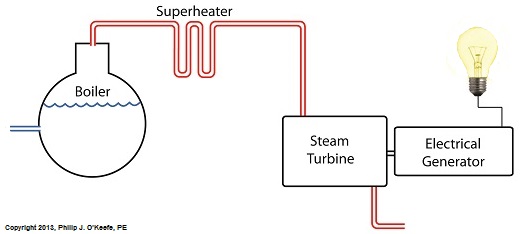
Power plants produce electrical energy for consumers to use, whether at home or for business, that’s obvious enough, but did you know that in order to produce that electrical energy they must first be supplied with heat energy? The heat energy that power plants crave comes from a fuel source, such as coal, oil, or natural gas, by way of a burning process. Once the heat energy is released from the coal through burning, it’s transported into a steam turbine by way of superheated steam, which is supplied to it by a piece of equipment named, appropriately enough, a superheater.
So what is a superheater and how does it function? Take a look at the illustration below.

The superheater looks like a W. It’s actually a cascading array of bent steam pipe, situated above a source of open flames which are produced by the burning of a fuel source. A photo of an actual superheater is shown below.

So how many bends are in a superheater? Enough to fill the needs of the particular power plant it is supplying energy to. Since all power plants are designed differently, we’ll keep things in general terms.
The many bends in the superheater’s pipes form a circuitous path for steam to flow as it follows a path from the boiler to the steam turbine. The superheater’s unique construction gives the steam flowing through it maximum exposure to heat. In other words, the bends increase the time it takes for the steam to flow through the superheater. The more bends that are present, the longer the steam will be exposed to the flame’s heat energy, and the longer that exposure, the more heat energy that is absorbed by the steam.
Superheating routinely results in temperatures in excess of 1000°F. This superheated steam is laden with abundant heat energy which will keep the steam turbine spinning and the generator operating. The net result is millions of watts of electrical power.
As we learned in a previous blog, the superheater is designed to provide the turbine with sensible heat energy to prevent steam from completely desuperheating, which would result in dangerous condensation inside the turbine.
The newly added superheater is a major improvement to a power plant’s water-to-steam cycle, but there’s still plenty of waste and inefficiency in the system, which we’ll discuss next week.
________________________________________ |
Tags: boiler, coal, coal power plant, condensing, electric utility power plant, electrical energy, electrical generator, engineering expert witness, flames, forensic engineer, heat energy, natural gas, oil, pipes, power engineer, power plant engineer, power plant training, sensible heat energy, steam, steam cycle, steam turbine, superheated steam, superheater, water cycle, water droplets
Posted in Engineering and Science, Expert Witness, Forensic Engineering, Innovation and Intellectual Property, Personal Injury, power plant training, Product Liability | Comments Off on Superheater Construction and Function
Sunday, August 25th, 2013
|
Last time we added a piece of equipment called a superheater, positioned between the boiler and steam turbine, to our basic electric utility power plant steam and water cycle. Its addition enables a greater and more consistent supply of heat energy to the steam which powers the turbine. How much more? Let’s look at Figure 1 to get an idea.

Figure 1
You may have noticed that our illustration lacks numerical representation. That’s because power plants are designed differently, depending on fuels used and power output required. So unless we’re talking about a particular power plant, number values would be impractical. For example, I could specify a boiling point of 596°F at 1,500 pounds per square inch (PSI), and a superheater outlet temperature of 1,050°F at 1,200PSI, and I could make note of esoteric things like enthalpy (British Thermal Units per pound mass) values on the Heat Energy axis. But to facilitate our discussion we’ll keep things simple and focus on the general process.
Figure 1 shows in phase D the additional heat energy being added to the steam, thanks to the superheater. This is significantly more than had been added by the boiler alone, as represented by phase C. The turbine consumes heat energy added in phases C and D and converts it into mechanical energy to drive the generator, resulting in electrical energy being provided to consumers in the most energy efficient way possible.
But increasing power output and efficiency isn’t the superheater’s only job. The heat it adds during phase D ensures the turbine’s safe operation when it’s cranking at full capacity, as represented by the superheated steam zones of phases C and D.
Next week we’ll discover how the superheater prevents a destructive process known as condensing from occurring inside the turbine.
________________________________________ |
Tags: boiler, boiling point, British Thermal Unit, coal power plant, coal power plant expert, condensing, destructive process, electric generator, electric utility power plant training, electrical energy, engineering expert witness, enthalpy, forensic engineer, fuel, heat energy, latent heat, mechanical energy, mechanical engineer, pounds per square inch, power engineer, power generation, power industry, power output, PSI, sensible heat, steam turbine, steam water cycle, superheated steam, superheater, turbine
Posted in Engineering and Science, Expert Witness, Forensic Engineering, Innovation and Intellectual Property, Personal Injury, power plant training | Comments Off on Superheating, Part 2
Monday, August 19th, 2013
|
Last time we learned that our power plant boiler as presently designed doesn’t do a good job of producing ample amounts of superheated steam, the kind of steam that turbines need to spin and power generators. During the process of superheating the more heat energy that’s added to the steam in our boiler, the higher its temperature becomes. However, our boiler can only produce a limited amount of superheated steam as it stands now.

So how do we get more heat energy into the superheated steam? Take a look at the illustration below for the solution to the problem.

You’ll note a prominent new addition to our illustration. It’s called a superheater.
The superheater performs the function of raising the temperature of the steam produced in our boiler to the incredibly high temperatures required to run steam turbines and electrical generators down the line, as explained in my blog on steam turbines. The superheater adds more heat energy to the steam than the boiler can alone.
In fact, the amount of heat energy in the superheated steam produced with our new design is proportional to the amount of electrical energy that power plant generators produce. Its addition to our setup will result in more energy supplied to the turbine, which in turn spins the generator. The result is more electricity for consumers to use and a more efficiently operating power plant.
But inefficiency isn’t the only problem addressed by the superheater. We’ll see what else it can do next week.
________________________________________
|
Tags: boiler, coal power plant training, coal-fired power plant, efficiency, electrical energy, electrical generator, engineering expert witness, forensic engineer, generator, heat energy, power engineer, power plant, power plant engineer, power plant operations, steam temperature, steam turbine, superheated steam, superheater, superheating, turbine
Posted in Engineering and Science, Expert Witness, Forensic Engineering, Innovation and Intellectual Property, Personal Injury, power plant training | Comments Off on Superheating, Part I
Monday, October 22nd, 2012
|
As we’ve come to know through this series of blogs, all electronic components pose some degree of internal resistance to the electric current flowing through them. This resistance results in electrical energy being converted into heat energy, heat which poses potential problems to sensitive components like electronic circuit boards. If things get hot enough, components fail and fires may ignite.
To address these issues engineers design circuits with resistors whose job it is to limit the current flowing to electrical components. In this article we’ll see how a limiting resistor protects a Zener diode from this fate, allowing it to continue doing its job of regulating voltage.
In our last blog we applied Ohm’s Law to our regulated power supply circuit, which makes use of a Zener diode. See Figure 1.
Figure 1
Ohm’s Law gave us the following equation to determine the amount of current, IPS, flowing from the unregulated power supply portion, through the current limiting resistor RLimiting, and making its way into the rest of the circuit:
IPS = (VUnregulated – VZener) ÷ RLimiting
We learned last week that for the circuit to work, the voltage of the unregulated power supply portion of the circuit, VUnregulated, must be greater than the Zener voltage, VZener.
Looking at the equation above, we see that the voltage difference is divided by RLimiting, the value of the limiting resistor in the circuit. This limiting resistor is there to constrain the current flowing to the Zener diode, allowing the diode to keep things under control within the circuit.
Basic mathematical principles hold that if a smaller number is divided by a bigger number, the resulting answer is an even smaller number. Applying this principle to the equation above, if RLimiting is a big number, then IPS must be a smaller number. On the other hand the smaller RLimiting gets, the bigger IPS becomes.
So what does it take for our circuit to fail? Remove the limiting resistor as shown in Figure 2 and the value for RLimiting disappears. In other words, RLimiting becomes zero.

Figure 2
In this case our Ohm’s Law equation becomes:
IPS = (VUnregulated – VZener) ÷ 0 = ∞
The resulting answer is said to go to infinity, or ∞, as it is represented mathematically. In other words, without a limiting resistor being employed within our circuit, IPS will become so large it will overwhelm the diode’s current handling capacity and lead to circuit failure.
Next time we’ll go over some advantages and disadvantages of this Zener diode voltage regulating circuit, and why the disadvantages outweigh the advantages for many applications.
____________________________________________ |
Tags: circuit boards, circuit design, current capacity, electric current flow, electrical energy, electronic components, engineering expert witness, engineers, fires, forensic engineer, heat energy, internal resistance, limit current flow, Ohm's Law, power supply, unregulated power supply, voltage regulator, Zener diode
Posted in Engineering and Science, Expert Witness, Forensic Engineering, Innovation and Intellectual Property, Personal Injury, Product Liability | Comments Off on Transistors – Voltage Regulation Part XIV
Monday, March 7th, 2011
| When I was a kid I remember how cool it was to have a headlight on my bike. Unlike the headlights that the other kids had, mine was not powered with flashlight batteries. The power came from a little gadget with a small wheel that rode on the front tire. As I pedaled along, the tire’s spinning caused the small wheel to spin, and voila, the headlight bulb came to life. Little did I know that this gadget was a simple form of electrical generator, and of course I was oblivious to the fact that a similar device, albeit on a much larger scale, was being used at a nearby power plant to send electricity to my home.
Over the last few weeks we learned how a coal fired power plant transforms chemical energy stored in coal into heat energy and then into mechanical energy which enables a steam turbine shaft to spin. We’ll now turn our attention to the electrical generator. It’s responsible for performing the last step in the energy conversion process, that is, it converts mechanical energy from the steam turbine into the desired end product, electrical energy for our use. It represents the culmination in energy’s journey through the power plant, the process by which energy contained in a lump of coal is transformed into electricity.
To show how this final energy conversion process works, let’s look at Figure 1, a simplified illustration of an electrical generator.

Figure 1 – A Basic Electrical Generator
You’ll note that the generator in our illustration has a shaft with a loop of wire attached to it. When the shaft spins, so does the loop. The shaft and wire loop are placed between the north (N) and south (S) poles of a horseshoe magnet. It’s a permanent magnet, so it always has invisible lines of magnetic flux traveling between its two poles. These magnetic lines of flux are the same type as the ones created by kids’ magnets, when they play with watching paperclips jump up to meet the magnet. The properties of magnets are not completely understood, even to adults who work with them every day. And what could be more mysterious than the fact that as the shaft and wire loop spin through the lines of magnetic flux in the generator, an electric current is produced in the wire loop.
Now, this current that’s flowing through the spinning wire loop is of no use if we can’t channel it out of the generator. The wire loop is spinning vigorously, so you can’t directly connect the ends of the loop to stationary wires. A special treatment is required. Each end of the loop is connected to a slip ring. A part called a “brush” presses against each slip ring to make electrical contact. The electrical current then flows from the loop through the spinning slip rings, through the brushes, and into the stationary wires. So, if, for example, a light bulb is connected to the other end of the stationary wires, this completes an electric circuit through which current can flow. The light bulb will glow as long as the generator shaft keeps spinning and the wire loop keeps passing through the magnetic lines of flux from the magnet.
So we see that the key to the whole energy conversion process is to have movement between magnetic lines of flux and a loop of wire. As long as this movement occurs, the electricity will flow. This basic principle is the same in a coal fired power plant, but the electrical generator is far more complicated in construction and operation than shown here. My Coal Power Plant Fundamentals seminar goes into far greater detail on this and other aspects of electricity generation, but what I have shared with you above will give you a basic understanding of how they operate.
That concludes our journal with coal through the power plant. This series of blogs has, you will remember, presented a simplified version of the complex material presented in my teaching seminars. Next week we’ll branch off, taking a look at why electrical wires come in different thicknesses.
_____________________________________________

|
Tags: bicycle, brush, coal power plant fundamentals, electric utility training, electrical energy, electrical generator, electricity from coal, electricty and magnetism, engineering expert witness, flux, forensic engineer, heat energy, lines of flux, magnetic field, mechanical energy, power engineering, power generation, power plant, power plant training, slip ring, steam turbine, training seminar, wire loop
Posted in Engineering and Science, Expert Witness, Forensic Engineering, Innovation and Intellectual Property, Personal Injury, power plant training | Comments Off on Coal Power Plant Fundamentals – The Generator


