| My wife and I have an agreement concerning the kitchen. She cooks, I clean. Plates and utensils are easy enough to deal with, especially when you have a dishwasher. Pots and pans are a little more challenging. But what I hate the most are the food processors, mixers, blenders, slicers and dicers. They’re designed to make food preparation easier and less time consuming, but they sure don’t make the clean up any easier! Quite frankly, I suspect the time involved to clean them exceeds the time saved in food preparation.
Food processors on a larger scale are also used to manufacture many food products in manufacturing facilities, and being larger and more complicated overall, they’re even more difficult to clean. For example, I once designed a production line incorporating a dough mixer for one of the largest wholesale bakery product suppliers in the United States. A small elevator was required to lift vast amounts of ingredients into a mixing bowl the size of a compact car. Its mixing arms were so heavy, two people were required to lift them into position. It was also my task to ensure that the equipment as designed was capable of being thoroughly cleaned in a timely and cost effective manner. Food processing machinery must be designed so that all areas coming into contact with ingredients can be readily accessed for cleaning. And since most of the equipment you are dealing with in this setting is far too cumbersome to be portable, the majority of the cleaning must be cleaned in place, known in the industry as CIP. To facilitate CIP, commercial machinery is designed with hatches and special covers that allow workers to get inside with their cleaning equipment. Small, portable parts of the machine, such as pipes, cutting blades, forming mechanisms, and extrusion dies, are often made to be removable so that they can be carried over to an industrial sized sink for cleaning out of place, or COP. These potable machine components are typically removable for COP without the use of any tools and are fitted with flip latches, spring clips, and thumb screws to facilitate the process. Everything in a food manufacturing facility, from production machinery to conveyor belts, is typically cleaned with hot, pressurized water. The water is ejected from the nozzle end of a hose hooked up to a specially designed valve that mixes steam and cold water. The result is scalding hot pressurized water that easily dislodges food residues. Bacteria doesn’t stand a chance against this barrage. The water, which is maintained at about 180°F, quickly sterilizes everything it makes contact with. It also provides a chemical-free clean that won’t leave behind residues. Once dislodged, debris is flushed out through strategically placed openings in the machine which then empty into nearby floor drains. As a consequence of the frequent cleanings commercial food preparation machinery requires, their parts must be able to withstand frequent exposure to high pressure water streams. Parts are typically constructed of ultra high molecular weight (UHMW) food-grade plastics and metal alloys such as stainless steels, capable of withstanding the corrosive effects of water. And since water and electricity make a dangerous combination, gaskets and seals on the equipment must be tight enough to protect against water making its way into motors and other electrical parts. Next time we’ll look at how design engineers of food manufacturing equipment use a systematic approach to minimize the possibility of food safety hazards, such as product contamination. ____________________________________________ |
Posts Tagged ‘elevator’
Food Manufacturing Challenges – Cleanliness
Monday, October 3rd, 2011Dynamic Brakes
Monday, May 31st, 2010|
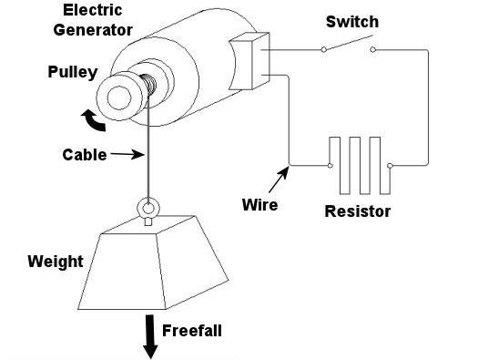
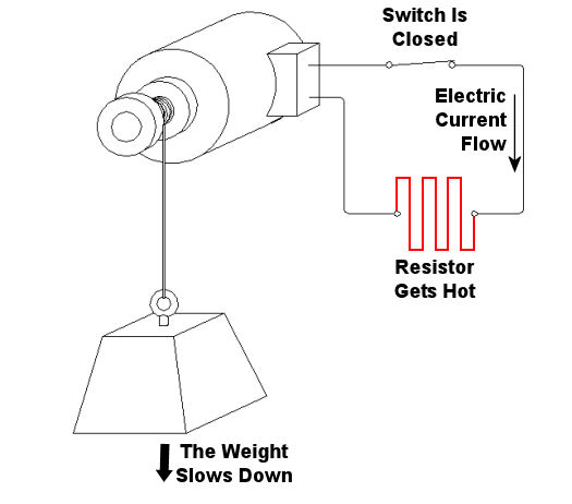
Last week we looked at how a mechanical brake stopped a rotating wheel by converting its mechanical energy, namely kinetic energy, into heat energy. This week, we’ll see how a dynamic brake works. Chances are you have directly benefited by a dynamic braking system the last time you rode in an elevator. But, to understand the basic principle behind an elevator’s dynamic brake system, let’s first take a look at the electric braking system in Figure 1 below. Figure 1 – A Simple Electric Braking System Here the brake consists of an electric generator wired via an open switch to an electrical component called a resistor. The weight is attached to a cable that is wound around a pulley on the generator’s shaft. As the weight freefalls, the cable unwinds on the pulley, causing the pulley to turn the generator’s shaft. Unlike last week’s mechanical brake which required a good deal of effort to employ, a dynamic braking system requires very little. All that needs to be done is to close a switch as shown in Figure 2 below. When the switch is closed, an electrical circuit is created where the resistor gets connected to the generator. The resistor does as its name implies: it resists (but doesn’t stop) the electrical current flowing through it from the generator. As the electrical current fights its way through the resistor to get back to the generator, the resistor gets hot like an electric heater. This heat is dissipated to the cooler surrounding air. At the same time, the weight begins to slow down in its descent. But how is this happening? The electric braking system can be thought of as an energy conversion process. We start out with the kinetic, or motion energy, of the freefalling weight. This kinetic energy is transmitted to the electrical generator by the cable, which spins the generator’s shaft as the cable unwinds. Electrical generators are machines that convert kinetic energy into electrical energy. This energy travels from the electric generator through wires and a closed switch to the resistor. In the process the resistor converts the electrical energy into heat energy. So, kinetic energy is drawn from the falling weight through the conversion process and leaves the process in the form of heat. As the falling weight is drained of kinetic energy, it slows down.
Figure 2 – Applying the Electric Brake Okay, now let’s get back to dynamic brakes on elevators. An elevator is attached by a cable to a hoist that is powered by an electric motor. When it’s time to stop at the desired floor, the automatic control system disconnects the elevator’s electric motor from its power source and turns the motor into a generator. The generator is then automatically connected to a resistor like the one shown in the electric brake above. The kinetic energy of the moving elevator is converted by the generator into electrical energy. The resistor converts the electrical energy into heat energy which is then dissipated into the surrounding environment. The elevator slows down in the process because it’s being robbed of kinetic energy. When the dynamic brake slows the elevator down enough, a mechanical brake is introduced, taking over to bring the elevator to a complete stop. This two-fold process serves to reduce wear and tear on the mechanical brake’s parts, lengthening the operational lifespan of the system as a whole. Next time, we’ll tie everything together and show how mechanical and dynamic brakes work together in a diesel locomotive. _____________________________________________ |


