|
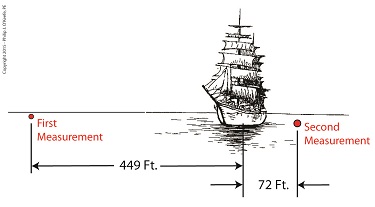
Last time we touched on the fact that bigger is better when it comes to using a rangefinder to measure extremely long distances. Today we’ll expand on that theme and discover how bigger is indeed more accurate. Returning to our previous example, we’re still trying to find the distance to that ship on the horizon. We’ve got two rangefinders at our disposal, one short, one long, and the measurements provided by them are vastly different. Which is correct? To find out, we’ll hypothesize that we’ve taken the time to meticulously measure the distance the hard way, with a really long tape measure. Doing so, we find the actual distance to the ship is 5280 feet. We can now compare the actual measured distance to the measurements taken with our two rangefinders and compare their accuracy: Rangefinder One = 5729 feet – 5280 feet = 449 feet Rangefinder Two = 5208 feet – 5280 feet = -72 feet The smaller rangefinder results in a difference, or error, of 449 feet, while the bigger results in a difference of 72 feet. It’s clear that the bigger rangefinder gets us closer to the actual measurement taken by tape measure, so it’s the most accurate. The obvious conclusion is that the bigger the rangefinder used, the smaller the error factor. That’s because as the length of the rangefinder increases, the smaller the angle θ becomes, a situation which results in the tangent of θ moving farther away from rather than closer to 90°, all of which translates to more accuracy in our rangefinder’s measurements. Put another way, the bigger the rangefinder, the less likelihood there is of its angle θ‘s tangent hovering near 90° and becoming asymptotic, an undesirable outcome for reasons explained in a previous blog in this series. Next time we’ll see how early astronomers were able to arrive at relatively accurate calculations of the distances between Earth and other heavenly bodies by using the parallax effect produced by the world’s largest optical rangefinder, Planet Earth itself. ____________________________________
|
Posts Tagged ‘engineering expert witness’
Optical Rangefinders, Bigger is More Accurate
Tuesday, April 14th, 2015Optical Rangefinders, Why Bigger is Better
Monday, April 6th, 2015|
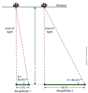
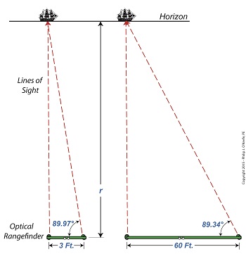
Last time we introduced the fact that ultra fine gradations must be applied to a rangefinder’s indicator gauge in order to make accurate measurements of extremely long distances. Today we’ll see how using a bigger rangefinder effectively solves this problem. Figure 1 illustrates the subject. The left side shows what happens when attempting to use a small rangefinder to measure the distance to that distant ship on the horizon. The right side shows how the situation is improved by using a large rangefinder, which serves to decrease the angle θ. Figure 1 You see it all boils down to the angle θ. When d is extremely short in comparison to the measured distance r, the angle θ creeps ever closer to becoming 90°, a situation which severely impacts the rangefinder’s accuracy due to the impact on the tangent of θ. For a refresher on that see last week’s blog. Let’s see what the situation looks like numerically. The smaller rangefinder has a length, d, equal to 3 feet. Using it we measure θ to be 89.97°. Plugging these numbers into the rangefinder distance measuring formula, we measure the distance to the ship to be: r = d × tan(θ) r = 3 feet × tan(89.97°) r = 5729 feet Now let’s take a second measurement with the bigger rangefinder on the right. This one has a length d equal to 60 feet. You might be asking yourself, Do they really come that big?? Yes, before radar technology came on the scene to take their place, it was possible to find rangefinders as big as 60 feet in length! Using the larger rangefinder we find θ is equal to 89.34° and the distance to the ship is calculated to be: r = d × tan(θ) r = 60 feet × tan(89.34°) r = 5208 feet Why are the measurements between the two rangefinders so different? Which one is more accurate? In short, bigger is better. We’ll see why next week. ____________________________________
|
Further Limitations of an Optical Rangefinder
Monday, March 30th, 2015|
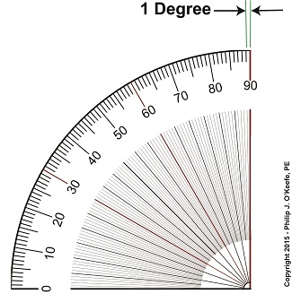
Last time we discovered that when optical rangefinders are used to measure the distance to objects extremely far away we encounter problems. We discussed one of them last time, the fact that as θ approaches 90° the tangent of θ becomes asymptotic, resulting in a situation where even the most minute changes to θ bring about huge corresponding changes to the distance, r, we seek to measure. This difficulty goes hand in hand with another we’ll be discussing today, the problem of very tight spaces. They both lead to a greater potential for measurement inaccuracies. The rangefinder in Figure 1 depicts the kind of situation that often results when attempting to measure objects that are extremely far away, like a ship on a distant horizon. Angle θ is very close to being 90°. Let’s see what that does to our measuring attempts with the rangefinder’s on-board measuring scale, its indicator gauge. The fact is, when a rangefinder’s indicator gauge hovers near 90°, it becomes user unfriendly. To illustrate, let’s refer to a common everyday protractor, shown in Figure 2. Protractors are divided into 1° gradations, which allow us to measure angles between 0° and 90°. This interval is fine for many angle measuring purposes, but we’ll see in a moment why it doesn’t work when measuring extremely long distances. A similar protractor is found on a rangefinder’s indicator gauge, enabling us to measure the angle θ. Notice how small the space is between 89 and 90 degrees. Now imagine having to split that area into hundreds, even thousands, more gradations in order to accurately assess the value of θ. This is precisely the situation we encounter when using a rangefinder to measure extremely long distances where the lines of sight form long, narrow triangles and θ hovers near 90°. Are you beginning to see — or rather not see — the problem? When this situation exists, ultra fine gradations must be made between the 89th and 90th degrees in order to make an accurate measurement of θ . This results in a situation where gradation marks are spaced so closely together they become difficult, if not impossible, for the unaided human eye to read. Next time we’ll see why bigger is indeed better when seeking to solve this problem. ____________________________________
|
Limitations of an Optical Rangefinder
Monday, March 23rd, 2015|
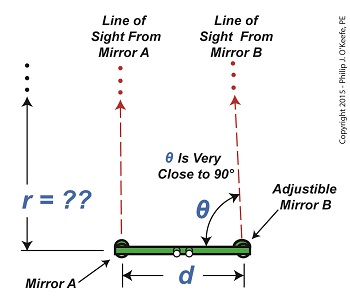
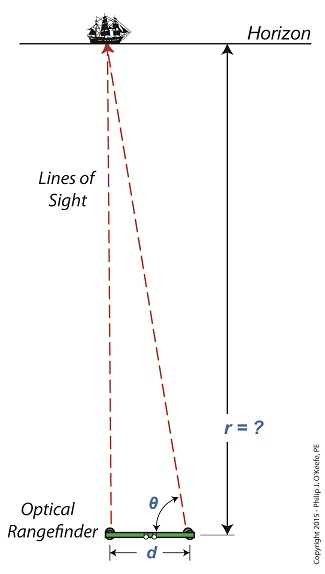
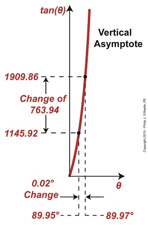
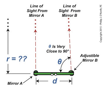
Last time we touched on the limitations of optical rangefinders when attempting to measure extremely long distances. Today we’ll expand on that theme. Let’s say we want to use a rangefinder to determine the distance, r, to an object that’s extremely far away, like a ship on a distant horizon, as shown in Figure 1. Figure 1 It’s obvious that the rangefinder’s length, d, is extremely small in comparison to the total distance viewed, r. When this situation exists, a very long and narrow right triangle is formed between the lines of sight provided by mirrors A and B of the rangefinder, represented by two red dashed lines, and the length of the rangefinder itself, d. It’s still a right triangle, a necessary condition to using our rangefinder formula to determine distance, however, when the triangle is an extremely long, narrow one, the angle θ approaches 90° in value. As discussed in a previous article, a θ value of 90° is impossible for the rangefinder distance formula to work with. The more distant the ship, the longer and narrower the triangle becomes, causing θ to creep ever closer to 90°. From a trigonometric point of view, this spells trouble. The problem is, the closer θ gets to 90°, the greater the disparity potential in its measurement. For example, let’s suppose that when the ship is first sighted with the rangefinder θ is measured at 89.95°. Then a second later the same person seeks to verify his measurement. Without noticing that he’s doing it, he shifts weight on his foot ever so slightly, takes a second reading, and finds that this time θ is 89.97°. That’s a difference of only 0.02° between readings, but it produces a huge change in the tan(θ). Figure 2 represents a graph of these two measurements, with the angle θ values on one axis, the tan(θ) values on the other. Figure 2 The graph illustrates how this minute change in θ of only two hundredths of a degree (0.02°) results in a correspondingly huge change to tan(θ) of 763.94 units. We know that the rangefinder’s length, d, equals 3 feet, so plugging all the numbers into our rangefinder formula we determine the distance to the ship to be, r = d × tan(θ) r = 3 feet × 763.94 = 2291.82 feet What this means on a practical usability level is that when the rangefinder’s adjustable mirror B moves only two one hundredths of a degree, it results in a change to the distance viewed, r, of almost half a mile! There’s another problem that goes hand in hand with the one presented today. We’ll explore it next time.
____________________________________
|
Vertical Asymptotes and Optical Distance Measurement
Friday, March 13th, 2015|
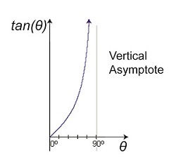
Last time we introduced the vertical asymptote and the fact that it’s associated with the tangent function when angles approach 90° in value. On a graph that looks like this: Figure 1This asymptotic relationship exists when attempting to use an optical rangefinder to determine the distance to objects that are extremely far away– as in so far away they can barely be seen by the naked eye. When this is the case, is it even possible to use the optical rangefinder? Theoretically, yes. But not without complications. Our attempt to use the rangefinder to do this is illustrated in Figure 2. Figure 2You’ll note that the lines of sight extending from mirrors A and B on our rangefinder are almost parallel to each other, creating a situation where a vertical asymptote will form with regard to θ’s tangent. In plain English this means that even minute changes in θ will result in huge changes to tan(θ). We’ll explore that subject next time.
____________________________________
|
Tangent and the Vertical Asymptote
Monday, March 2nd, 2015|
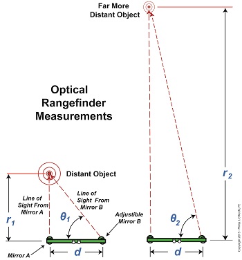
Imagine working, working, working towards a goal and getting oh so close, but never being able to actually reach it. It’s happened to all of us some of the time, but with vertical asymptotes it happens all of the time. We’ll see why the nature of vertical asymptotes presents a problem when measuring extreme distances in today’s blog. We’ve found that optical rangefinders can be useful in measuring long distances. They work well in many situations, but not all. When it comes to extremely long distances they aren’t at all helpful. That’s due to problems presented by trigonometry, more specifically the tangent function and how it leads to vertical asymptotes. Let’s look at Figure 1 to bear this out. Figure 1
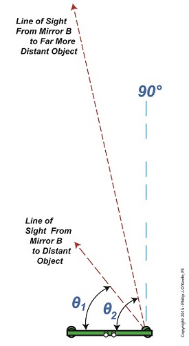
In Figure 1 we see the same rangefinder being used to view objects at two different distances, one distance far greater than the other. There’s an obvious difference in the lengths of the sides of the triangles formed, as well as an obvious difference in angles θ1 and θ2. θ2 is much steeper than θ1. This is more apparent when the lines of sight are isolated, as shown in Figure 2. Figure 2
Figure 2 shows that as an object becomes more distant and r, the distance to the object viewed increases, the angle θ gets closer and closer to a value of 90°. What’s significant about this is that a θ value of 90° is impossible for a rangefinder to work with. Why? Because it uses trigonometry to measure distances, more specifically the tangent function within trigonometry, and when θ takes on a value of 90°, it becomes asymptotic in nature — a situation which renders the optical rangefinder useless. To visualize this, we’ve plotted the tangent function for an array of angle θ values on a graph in Figure 3. Figure 3
The curved line represents plotted tangent values for θ that fall between 0° and 90°. What it demonstrates is that as θ gets closer to becoming 90°, it becomes more vertical and steeper in incline. In other words, it forms a vertical asymptote, stretching to reach a value of 90° but never actually getting there. In the math world this means that the tangent’s value is on its way to becoming unbounded or undefined. In plain English this means that the tangent’s value becomes increasingly more unworkable. In fact, the tangent of 90° degrees does not exist. Try entering the number 90 into your calculator and pressing the TAN button. You’ll receive an error message in return. Next week we’ll see the impact this has on the function of an optical rangefinder when the object viewed is so far away the angle θ approaches a value of 90°.
____________________________________
|
How An Optical Rangefinder Uses Trigonometry
Monday, February 23rd, 2015|
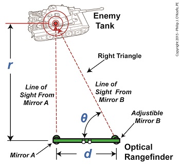
We left off with an artillery soldier spotting an enemy tank in the distance. Luckily, he’s got an optical rangefinder at his disposal to measure the distance between them and crank out an accurate shot. His first action is to peer through the rangefinder’s eyepieces, rotating the adjustable mirror on the right eyepiece until the tank comes into focus. The two lines of sight provided by the left and right eyepieces of the rangefinder form a right triangle due to the parallax effect. One of the angles in this triangle is designated on the illustration by the angle θ, and that’s the angle we’ll be working with. The fact that a right triangle exists means the distance, r, to the tank can be easily measured using principles found in trigonometry, a branch of mathematics that addresses the properties of triangles, hence, the prefix tri in its name. Tangent, and other trigonometric functions like sine and cosine, relate the angles of a right triangle to the ratios of the lengths of the sides of the triangle. In our case we’re concerned with the tangent, which is simply the value that’s derived by dividing the length of the side opposite to the angle θ by the length of its adjacent side. This value can be found in most trigonometry textbook tables, but is most easily found by using a calculator. Simply enter the angle θ‘s value, then press the TAN button. So how does the artillery soldier determine θ‘s value? With the tank in clear focus, it’s easily measured with an indicator gauge attached to the adjustable mirror near the right eyepiece on an optical rangefinder. Our soldier reads the gauge and determines that θ is equal to 89.935°, so the tangent of θ is equal to: tan(θ) = tan(89.935°) = 881.473 Now that we’ve determined the values for d and the tangent of the angle θ, we can plug those numbers into our equation to determine r, the distance to the enemy tank using the equation, r = d × tan(θ) Plugging in numerical values, the equation becomes, r = 3 feet × 881.473 = 2644.419 feet The distance to the tank is 2644.419 feet. Next time we’ll see how the peculiarities of the tangent function place limitations on the accuracy of optical rangefinders over extremely long distances. ____________________________________
|
What’s Inside an Optical Rangefinder
Friday, February 13th, 2015|
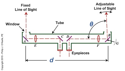
Last time we covered the mirrors found inside an optical rangefinder. Today we’ll discuss its other components, magnifying lenses E and F and the indicator gauge, G. See Figure 1. Figure 1 Magnifying lenses E and F are positioned in such a way that the two horizontal lines of sight reflecting off mirrors C and D pass through them on their way to mirrors A and B. Lenses E and F are adjustable, allowing the viewer to manipulate them until the distant image being viewed is seen in clear focus through both eyepieces, just as would happen with binoculars. To see the rangefinder in action let’s go out to the battlefield, where it’s routinely used. A soldier notices an enemy tank off in the distance. To make an accurate hit with his artillery he must determine the distance r from his position to the tank. The soldier in charge of this task observes the tank through the rangefinder’s eyepieces and manually adjusts lenses E and F until it comes into focus. He then adjusts the rangefinder’s mirror B until the line of sight extending from it converges on the tank along with the fixed line of sight from mirror A as shown in Figure 2. When the two images converge a right triangle is formed, and as we learned in a previous article, this fact will enable us to calculate r by using trigonometry with this formula: r = d × tan(θ) We already know that the value of d, the distance between mirrors A and B, is three feet. All that is left to be determined is the angle θ that’s formed between adjustable mirror B‘s forward line of sight out the tube’s opening and the horizontal line of sight between D and B. The last component within an optical rangefinder to be discussed is the indicator gauge, notated as G in Figure 1. This gauge is attached to mirror B inside the tube and is used to measure the angle θ that’s produced as the mirror is adjusted. When the lines of sight from mirrors A and B converge and the tank comes into clear view through the eyepieces, the value of θ can be read on the gauge’s numerical graduated scale, which is located on the exterior of the tube. Next time we’ll see how trigonometry and the study of right triangles prove indispensable when measuring distances with an optical rangefinder. ____________________________________
|
The Mirrors Inside an Optical Rangefinder
Friday, February 6th, 2015|
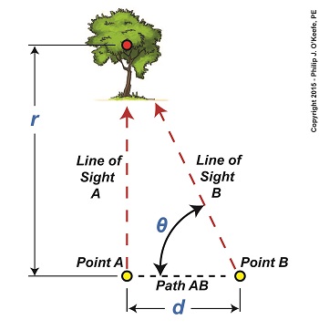
Last time we touched on the fact that humans require instruments to facilitate the optical measurement of distance to faraway objects, such as is represented by r in Figure 1. Figure 1 Today we’ll take a look at the mirrors inside an optical rangefinder, one of the devices that’s commonly used to measure great distances. The internal workings of an optical rangefinder are shown in Figure 2. Figure 2 The rangefinder’s body is a straight tube containing fixed mirrors, A, C, and D, and an adjustable mirror, B. Mirrors A and B in Figure 2 are analogous to Points A and B in Figure 1. For the sake of our example, we’ll say that the distance d in Figure 2 is equal to the distance d in Figure 1. This distance is three feet. The rangefinder functions similarly to a pair of binoculars, but with a twist — literally. Its four internal mirrors redirect the straight-ahead perspective that’s provided by the eyepieces into sideways orientations. Sight is deflected by mirrors C and D off to the left and right, respectively, as represented by red dashed lines. Finally, the lines of sight are once again aligned into straight-ahead orientations as they reflect off mirrors A and B and are guided out the openings at either end of the tube. Adjustable mirror B‘s line of sight is positioned at an angle that’s represented by the Greek letter θ, a symbol commonly used to represent angles in mathematics, engineering, and science. This angle is formed between mirror B’s line of sight and the horizontal line of sight traversing the expanse between mirrors D and B. The reason mirror B is an adjustable mirror is so that the line of sight extending from the opening at its location can converge into the line of sight provided by mirror A. Mirror B is manually manipulated until the image seen through it becomes one with A‘s image. Until this convergence takes place two separate images are seen through A and B. Next week we’ll see what happens when the images converge, and we’ll cover the remaining components within an optical rangefinder, items E, F, and G. ____________________________________
|
Parallax and Trigonometry
Monday, January 26th, 2015|
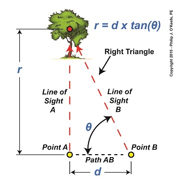
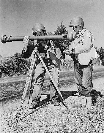
We’ve been working on a way to calculate the distance to a tree situated blocks from our viewing point. Flying raptors, such as our beloved bald eagle, wouldn’t find this in the least bit challenging. They’re able to accurately judge distances due to their special shape-shifting eye lenses which are capable of actually changing curvature spontaneously. But human physiology isn’t equipped for this task, so we’ll have to employ other methods. Today we’ll see how a branch of mathematics known as trigonometry comes into play. Referring to the illustration, we’d like to calculate the distance, r. You’ll note that a right triangle is formed by Line of Sight A, Path AB, and Line of Sight B. As mentioned in our last blog, right triangles are special because the relationship that exists between their sides and their internal angles is well defined within mathematics. In fact, we can calculate r by using this trigonometric formula, r = d × tan(θ) where d is the length of Path AB, θ is the angle between Line of Sight B and Path AB, and tan(θ) is the trigonometric function known as the tangent. Tangent, and other trigonometric functions like sine and cosine, relate the angles in a right triangle to the ratios of the lengths of the sides of the triangle. If we know two of the variables present in the equation presented above, we can determine the third, and the fact that there’s a right triangle present makes that task so much easier. As things stand now we have two unknowns, d and θ. As pointed out last week, the distance, d, is short, so we’ll use a tape measure to determine its length. Let’s say it measures out to be three feet. Now we need to solve for the angle θ that’s formed between Path AB and Line of Sight B. That’s a bit more challenging. There are a number of devices that can be used to measure θ, including a handheld magnetic compass. However, using a compass often yields inaccurate results, thereby increasing the likelihood of mistakes. A more accurate device to use would be an optical rangefinder, as shown below. The optical rangefinder is a device that’s often used in the military to measure long distances by using the principle of parallax. It functions much like binoculars do, but with a twist, literally, as we’ll see next time. ____________________________________
|
