Posts Tagged ‘engineering expert’
Wednesday, January 20th, 2016
|
In my work as an engineering expert I’ve never had to convert Joules of work-energy into calories, but that’s exactly what we’ll be doing together today. Last time we applied the Work-Energy Theorem to the progress of Santa’s sleigh and found that an opposing wind force of 3848.7 Newtons –or 865.2 pounds for those of us who are American– slowed his team from an initial velocity of 90 meters per second to a final velocity of 40 meters per second and that it happened over a distance of 760 meters. Today we’ll see how many calories the reindeer need to expend to get them back up to full delivery speed.

Prancer Loves Oats
Now we know that Santa successfully made all his deliveries on time this past Christmas, so that means that at some point his reindeer team was able to get back up to full sleigh-flying speed. They did it by expending extra energy. We’ll use the Work-Energy Theorem to find out how much energy that equates to. Here’s the Theorem again,
W = ½ × m × [v22 – v12]
where W is the work/energy required to speed up the sleigh team’s mass, m, from an initial velocity v1 to a final velocity v2. For a refresher on the special relationship between work and energy, see our past blog on the subject.
If Santa’s sleigh has a mass of 900 kilograms and its speed must increase from 40 to 90 meters per second, then the work required to do so is calculated as,
W = ½ × (900 kilograms) × [(90 meters/second)2 – (40 meters/second)2]
W = ½ × (900 kilograms) × (6,500 meters2/second2)
W = 2,925,000 kilogram2 · meters2 per second2 = 2,925,000 Joules
So Rudolph and his buddies had to expend 2,925,000 Joules of energy to perform 2,925,000 Joules of work. To understand where Rudolph and his team got that energy, we must state things in terms of nutritional value, that is, units of calories.
Did you know that 1 calorie is equal to 4,184.43 Joules? Applying that equivalency to our situation we get,
Nutritional Energy Required = (2,925,000 Joules) × (4,184.43 Joules/calorie)
= 699.02 calories
The net result is Santa’s team expended a total of 699.02 calories for all the reindeer to regain their full speed of 90 meters per second. That’s the nutritional energy found in slightly more than one cup of oats. Now everybody knows that Santa takes good care of his reindeer, so undoubtedly they were fed plenty of oats and hay before takeoff. This was stored in their body fat for future, on-demand use.
Sadly, Christmas is over, and it’s time to get back to the more mundane aspects of life. Next time we’ll apply the principles behind the Work-Energy Theorem to calculate the braking force required to stop a car in motion.
Copyright 2015 – Philip J. O’Keefe, PE
Engineering Expert Witness Blog
____________________________________ |
Tags: calories, energy, engineering expert, Joules, mass, speed, velocity, work, work-energy theorem
Posted in Engineering and Science, Expert Witness, Forensic Engineering, Innovation and Intellectual Property, Personal Injury, Product Liability | Comments Off on Work and Energy, Speed, and Calories
Monday, January 11th, 2016
|
Last time my engineering expertise was put to the test when it was discovered that Santa’s sleigh was being hampered by a strong gust of wind. At that time we introduced the Work-Energy Theorem to determine how strong the wind’s opposing force was, and today we’ll work with the Theorem to compute just what Rudolph was up against. Here again is the expanded, workable version of the Work-Energy Theorem as introduced last time,
F × d = ½ × m × [v22 – v12]
where F is a force acting upon a moving object of mass m over a distance d to slow it from an initial velocity of v1 to a final velocity of v2.
Applying the Theorem to the dynamics at play in Santa’s situation, F is the opposing wind force, which acts over a distance, d, to slow his sleigh from an initial velocity of v1 to a final velocity, v2, thus presenting Rudolph and his buddies with a real delivery challenge.
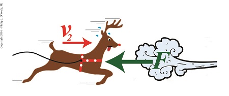 Rudolph Struggles Against a Fierce Wind Rudolph Struggles Against a Fierce Wind
If we know that Santa, his sleigh and reindeer have a combined mass of 900 kilograms — which is pretty standard for a fully loaded sleigh and reindeer team — and their initial velocity was 90 meters per second, final velocity 40 meters per second, and the distance over which the slowing took place was 760 meters, then the formula to calculate the opposing wind force becomes,
F × d = ½ × m × [v22 – v12]
F = ½ × m × [v22 – v12] ÷ d
F = ½ × (900kg) × [(40 meters/sec)2 – (90 meters/sec)2] ÷ 760 meters
F = -3848.7 Newtons = -865.2 Pounds
The minus sign signifies that the wind must exert an opposing force of 865.2 pounds in order to slow Santa’s sleigh down.
In order for Santa to get back on his delivery schedule, Rudolph is going to have to make up for lost time by expending extra energy. We’ll see how he does that next time.
Copyright 2015 – Philip J. O’Keefe, PE
Engineering Expert Witness Blog
____________________________________ |
Tags: distance, engineering expert, force, mass, Newtons, pounds, velocity, Work-EnergyTheorem
Posted in Engineering and Science, Expert Witness, Innovation and Intellectual Property, Personal Injury | Comments Off on The Work-Energy Theorem Applied to Santa’s Sleigh
Friday, January 1st, 2016
|
As an engineering expert I’ve applied the Work-Energy Theorem to diverse situations, but none as unique as its most recent application, the progress of Santa’s sleigh. Last week we saw how Santa and his reindeer team encountered a wind gust which generated enough force to slow them from an initial velocity of v1 to a final velocity, v2, over a distance, d. Today we’ll begin using the Work-Energy Theorem to see if Santa was able to keep to his Christmas delivery schedule and get all the good boys and girls their gifts in time.
Before we can work with the Work-Energy Theorem, we must first revisit the formula it’s predicated upon, de Coriolis’ formula for kinetic energy,
KE = ½ × m × v2 (1)
where, KE is kinetic energy, m is the moving object’s mass, and v its velocity.
The equation behind the Work-Energy Theorem is,
W = KE2 – KE1 (2)
where W is the work performed, KE1 is the moving object’s initial kinetic energy and KE2 its final kinetic energy after it has slowed or stopped. In cases where the object has come to a complete stop KE2 is equal to zero, since the velocity of a stationary object is zero.
In order to work with equation (2) we must first expand it into a more useful format that quantifies an object’s mass and initial and final velocities. We’ll do that by substituting equation (1) into equation (2). The result of that term substitution is,
W = [½ × m × v22 ] – [½ × m × v12] (3)
Factoring out like terms, equation (3) is simplified to,
W = ½ × m × [v22 – v12] (4)
Now according to de Coriolis, work is equal to force, F, times distance, d. So substituting these terms for W in equation (4), the expanded version of the Work-Energy Theorem becomes,
F × d = ½ × m × [v22 – v12] (5)
Next time we’ll apply equation (5) to Santa’s delivery flight to calculate the strength of that gust of wind slowing him down.
Copyright 2015 – Philip J. O’Keefe, PE
Engineering Expert Witness Blog
____________________________________ |
Tags: de Coriolis, distance, energy, engineering expert, force, kinetic energy, mass, velocity, wind force, work, work-energy theorem
Posted in Engineering and Science, Expert Witness, Forensic Engineering, Innovation and Intellectual Property, Personal Injury | Comments Off on The Math Behind the Work-Energy Theorem
Thursday, December 10th, 2015
|
My work as an engineering expert has often required that I perform calculations to quantify the energy consumed by electric motors and steam turbines, such as when they work together at power plants to generate electricity. Today we’ll see how work and energy share an interesting relationship that is brought out by examining the units by which they are measured.
Last time we used de Coriolis’ formula to compute work to calculate the amount of work performed while pushing a loaded wheelbarrow a distance of 3 meters. We found that in order to move the wheelbarrow that distance, a gardener must exert a force equal to 534 Newton • meters of work. That relationship is shown here,
Work = 178 Newtons × 3 meters = 534 Newton • meters (1)

de Coriolis’ Formula to Compute Work
The Newton, as discussed previously in this blog series, is shorthand notation for metric units of force, and we’ll use those units today to demonstrate the special relationship between work and energy.
We’ll start by supposing that you’re unfamiliar with the Newton as a unit of measurement. In that case you’d have to employ longhand notation to quantify things, which means you’d be measuring units of force in terms of kilogram • meters per second2.
Putting equation (1) in longhand notation terms, we arrive at,
Work = 178 kilogram • meters per second2 × 3 meters (2)
Work = 534 kilogram • meters2 per second2 (3)
If you’ve been following along in this blog series, you’ll recognize that the unit of measurement used to compute work, namely, kilogram • meters2 per second2, is the same as was used previously to measure energy. That unit is the Joule, which is considerably less wordy.
Equations (2) and (3) bear out the interesting relationship between work and energy — they share the same unit of measure. This relationship would not be apparent if we only considered the units for work presented in equation (1).
So following standard engineering convention where work and energy are expressed in the same units, the work required to push the wheelbarrow is expressed as,
Work = 534 Joules
Yes, work and energy are measured by the same unit, the Joule. But, energy isn’t the same as work. Energy is distinguished from work in that it’s the measure of the ability to perform work. Stated another way, work cannot be performed unless there is energy available to do it, just as when you eat it provides more than mere pleasure, it provides your body with the energy required to perform the work of pushing a wheelbarrow through the garden.
Next time we’ll see how work factors into the Work Energy Theorem, which mathematically relates work to energy.
Copyright 2015 – Philip J. O’Keefe, PE
Engineering Expert Witness Blog
____________________________________ |
Tags: de Coriolis' formula to compute work, electric motors, energy, engineering expert, generate electricity, joule, Newton meters, Newtons, power plants, steam turbines, unit of energy, units of force, work, work energy relationship, work required
Posted in Engineering and Science, Expert Witness, Forensic Engineering, Innovation and Intellectual Property, Personal Injury, power plant training, Product Liability | Comments Off on Work and Energy Share an Interesting Relationship
Sunday, November 29th, 2015
|
Although I’m an engineering expert in the 21st Century, I often have to employ engineering principles that are centuries old. A case in point is Gaspard Gustave de Coriolis‘ formula to compute work, as set out in his Principle of Work. We’ll work with his formula today, and we’ll introduce a unit of measurement used to quantify work known as the Newton.
de Coriolis’ formula to compute work is used to determine the amount of work, that is, the amount of dynamic energy available to influence the movement of an object, and is calculated by the formula,
Work = Force × Distance
where F represents the force acting upon an object that travels a distance of D. Force is most often expressed in metric units as kilogram • meter per second2, a wordy expression which is more conveniently referred to as the Newton.
In the image below, F is the force of 178 Newtons exerted by the gardener to push his filled wheelbarrow a distance of 3 meters. The quantity 178 Newtons was obtained by way of direct personal experience working in my own garden. I’ve found that it takes approximately 40 pounds of force to push a wheelbarrow loaded with dirt across level ground. Because one pound of force is equal to 4.45 Newtons, the amount of force I exerted is expressed as,
[40 pounds of force] × [4.45 Newtons per pound force] = 178 Newtons

Work = Force × Distance
If 178 Newtons of force is required to push the wheelbarrow a distance of 3 meters, then the work performed is expressed as,
Work = 178 Newtons × 3 meters
= 534 Newton • meters
Next time we’ll explore the special relationship between work and energy and introduce another unit used to quantify work.
Copyright 2015 – Philip J. O’Keefe, PE
Engineering Expert Witness Blog
____________________________________ |
Tags: de Coriolis' formula to compute work, distance, energy, engineering expert, force, Gaspard Gustave de Coriolis' principle of work, Newton, work formula
Posted in Engineering and Science, Expert Witness, Innovation and Intellectual Property, Personal Injury | Comments Off on de Coriolis’ Formula to Compute Work and the Newton
Sunday, November 15th, 2015
|
I was recently retained as an engineering expert in a lawsuit in which I had to determine the force acting upon an object. In order to quantify that force, I employed Gaspard Gustave de Coriolis‘ Principle of Work, an engineering concept he introduced in his 1829 textbook, Calculation of the Effects of Machines. We’ll take our first look at de Coriolis’ Principle of Work today, along with the term he used to quantify work, the dynamode.
As a scientist living during the time of the great Industrial Revolution, de Coriolis was interested in lots of things, and he was particularly interested in quantifying the effort involved to accomplish tasks, like how many men, horses, or steam engines were required to move a stationary object. He defined this activity as work, and he hoped its study would lead to a broadly accepted engineering principle which could be applied across industrial functions.
According to de Coriolis, work is the force acting upon a stationary object which causes it to move, multiplied by the distance moved. Work could also be defined as the force acting upon an object already in motion, multiplied by the distance traveled before it comes to a stop.
To quantify work, de Coriolis proposed the dynamode as its unit of measure, a term which derives from the Greek words dynamis, meaning power, and odos, meaning path. He went on to define one dynamode as the amount of work required to lift an object with a mass of 1,000 Kg, or kilograms, one meter above the ground.
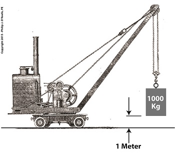
de Coriolis’ Dynamode Quantity
Catchy as it may sound, the word dynamode is all but forgotten today. But de Coriolis’ Principle of Work and his formula to calculate work remain to the present day as fundamental concept in engineering. We’ll present that formula next time.
Copyright 2015 – Philip J. O’Keefe, PE
Engineering Expert Witness Blog
____________________________________ |
Tags: de Coriolis’ Principle of Work, dynamode, engineering expert, joule, lawsuit, work
Posted in Engineering and Science, Forensic Engineering, Innovation and Intellectual Property, Personal Injury, Product Liability | Comments Off on de Coriolis’ Principle of Work and Dynamode
Tuesday, November 3rd, 2015
|
When acting as an engineering expert I’m often called upon to investigate incidents where energy converts from one form to another, a phenomenon that James Prescott Joule observed when he built his apparatus and performed his experiments with electricity. Today we’ll apply Joule’s findings to our own experiment with a coffee mug when we convert its kinetic energy into electrical energy and see how the units used to express that energy also change.
We had previously calculated the kinetic energy contained within our falling coffee mug to be 4.9 kg • meter2/second2, also known as 4.9 Joules of energy, by using de Coriolis’ Kinetic Energy Formula. Now most of us don’t speak in terms of Joules of energy, but that’s easily addressed. As we learned in a previous blog on The Law of Conservation of Energy, all forms of energy are equivalent and energy can be converted from one form to another, and when it does, the unit of energy used to express it also changes.
Let’s say we want to put our mug’s 4.9 Joules of kinetic energy to good use and power an electric light bulb. First we must first find a way of converting the mug’s kinetic energy into electrical energy. To do so, we’ll combine Joule’s apparatus with his dynamo, and connect the mug to this hybrid device with a string.
![]() 
Converting Kinetic Energy to Electrical Energy
As the mug falls its weight tugs on the string, causing the winding drum to rotate. When the drum rotates, the dynamo’s magnet spins, creating electrical energy. That’s right, all that’s required to produce electricity is a spinning magnet and coils of wire, as explained in my previous blog, Coal Power Plant Fundamentals – The Generator.
Now we’ll connect a 5 Watt bulb to the dynamo’s external wires. The Watt is a unit of electrical energy named in honor of James Watt, a pioneer in the development of steam engines in the late 18th Century.
Now it just so happens that 1 Watt of electricity is equal to 1 Joule of energy per a specified period of time, say a second. This relationship is expressed as Watt • second. Stated another way, 4.9 Joules converts to 4.9 Watt • seconds of electrical energy. Let’s see how long we can keep that 5 Watt bulb lit with this amount of energy. Mathematically this is expressed as,
Lighting Time = (4.9 Watt • seconds) ÷ (5 Watts) = 0.98 seconds
This means that if the mug’s kinetic energy was totally converted into electrical energy, it would provide enough power to light a 5 Watt bulb for almost 1 second.
Next time we’ll see what happens to the 4.9 Joules of kinetic energy in our coffee mug when it hits the floor and becomes yet another form of energy.
Copyright 2015 – Philip J. O’Keefe, PE
Engineering Expert Witness Blog
____________________________________ |
Tags: coils of wire, dynamo, electrical energy, engineering, engineering expert, James Prescott Joule, James Watt, joule, kinetic energy, magnet, power, watt seconds, wires
Posted in Engineering and Science, Innovation and Intellectual Property, power plant training | Comments Off on Converting Kinetic Energy to Electrical Energy
Saturday, October 24th, 2015
|
As an engineering expert with 14 years’ electric utility experience, I’ve dealt with all types of electrical power generators, including many similar to the dynamo that James Prescott Joule used in his Experiment With Electricity. Today we’ll look inside Joule’s dynamo and see how it contributed to creating electricity as well as another of Joule’s discoveries, the Joule Heating Effect.

Dynamo-Circa Early 19th Century
In Joule’s Experiment With Electricity, the dynamo was powered by a steam engine, which enabled the dynamo’s shaft to spin. As it spun, the magnet located inside the dynamo also spun, thus creating a rotating magnetic field that surrounded the dynamo’s internal copper wire coils.
The interaction between the magnetic field and wire produced electric current which flowed inside the coils. The current ultimately made its way out of the dynamo by way of external wires, to which any number of devices could be powered when attached. The net result was the engine’s mechanical energy had been converted into electrical. To learn more about the process of producing electricity with magnets see my blog on, Coal Power Plant Fundamentals – The Generator.
As electrical energy flowed through the dynamo’s wiring, some of it was converted into heat energy. This was due to resistance posed by impurities present in the makeup of the wire, impurities which served to impede the overall flow of electric current. When electrons flowing through the wire collided with these impediments, they caused heat to build up inside the wire, a phenomenon which came to be known as the Joule Heating Effect. To read more on electrical resistance and Joule heating go to my blog, Wire Size and Electric Current.
The net result of Joule’s Experiment With Electricity was to further prove the link between chemical, heat, mechanical and electrical energies as set out in the Law of Conservation of Energy. And I suspect that knowledge was later put to use by Joule’s family for the betterment of their brewery business.
Next time we’ll use Joule’s experimental findings in conjunction with de Coriolis’ Kinetic Energy Formula to quantify the energy of the falling coffee mug we’ve been watching.
Copyright 2015 – Philip J. O’Keefe, PE
Engineering Expert Witness Blog
____________________________________ |
Tags: de Coriolis, dynamo, electric utility, electrical energy, electrical power generators, electrical resistance, engineering expert, heat energy, James Prescott Joule, Joule heating, Joule's experiment with electricity, law of conservation of energy, power plant, wire size and electric current
Posted in Engineering and Science, Expert Witness, Forensic Engineering, Innovation and Intellectual Property, Personal Injury, power plant training, Product Liability | Comments Off on Joule’s Dynamo – The Joule Heating Effect
Monday, June 17th, 2013
|
Movies, that is 3D animations, are moving into the courtroom, and intended messages are made clearer than ever as a result. If a picture is worth a thousand words, how much more effective is a moving 3D image?
We’ve been viewing a static two-dimensional representation of a machine for the past two blogs. Have you been able to figure it out yet? Here it is again:

Would it help you to understand if I identified it as a piece of food manufacturing equipment equipped with a rake that aligns cookies on a conveyor belt? Would that verbal description allow you to “see” in your mind’s eye how it operates? Unless you had the right technical background, it’s unlikely.
Last week we introduced the verbiage person of ordinary skill in the art as a term widely used within patent litigation. This person is said to have the ability to interpret and understand patent drawings, and they typically possess a technical and/or scientific background.
But what if participants in a legal proceeding lack this background? Technical experts are often hired on as consultants to attorneys, and in some instances, judges, when clarification is required. These experts provide technical expertise and tutorials on the technology involved in complex cases, and it happens with regularity when the operation of a patented device is in question.
By employing 3D animations the expert can show how the device operates, rather than attempt to explain it using the technical language of their profession. The expert works closely with an animation artist to create the animation, providing the technical information that the animator will use to create the fully functional model. Animators do not typically have the technical background to accomplish this on their own and will require an ongoing dialog with the technical expert to create the animation.
And now the moment we’ve all been waiting for. Here is our static image brought to life through animation:
The animation commands the viewer’s attention and holds their interest, even if they have no background in engineering or science, and the device’s function is now made clear. It must be noted that in the patent drawing, part of the mechanism lies in front of a steel divider plate and part behind, but for purposes of clarity the entire mechanism has been shown to the front of the plate. Now there’s no doubt as to how the parts move together to even up the rows of cookies on the conveyor belt.
Next week we’ll talk about juries, perception, and the advantages of using courtroom animations when at trial.
___________________________________________
|
Tags: 3D animation of patent drawings, 3D animations, animator, complex cases, consulting expert, conveyor belt, courtroom animations, courtroom demonstratives, courtroom visual, engineering expert, engineering expert witness, food manufacturing equipment, function, machine, opertion, patent case, patent infringement, patented device, technical expert, technical expertiese, technology, tutorial, tutorials
Posted in Courtroom Visual Aids, Engineering and Science, Expert Witness, Innovation and Intellectual Property, Personal Injury, Product Liability | Comments Off on Courtroom Animations – Bringing Patents to Life
Monday, April 9th, 2012
| I’m not a big fan of amusement parks. The first time I rode on a Tilt-A-Whirl I was caught off guard and flung onto my side by the centrifugal force acting upon my body, the lower half of which was constrained by a seat belt so I wouldn’t be catapulted out during the ride. To make matters worse, the centrifugal force started to force the lunch I’d made the mistake of eating just before back up my throat. It was a very unpleasant experience to say the least.
Centrifugal force is an interesting phenomenon, and its principles are involved in the operation of a centrifugal clutch, which we’ll see later. For now, let’s get a basic understanding of what it’s all about, thanks to the discoveries of Sir Isaac Newton in the late 17th Century.

Figure 1
Figure 1 shows a red ball, whose mass we’ll notate m, attached to a string, the other end of which is attached to a fixed point, such as if you held it taught between your fingers. If you’re in a playful mood, you might enjoy twirling the ball above your head on its string. The distance between the center of the ball and the fixed point is labeled r, which stands for the radius of the circular path traveled by the ball as it twirls around the fixed point. The speed at which the ball travels through the air is called its straight line velocity, or tangential velocity in scientific-speak, and it is generally notated as a V. The centrifugal force, or Fc, that is exerted upon the ball as it whirls around your head is, Sir Isaac tells us, measured by the equation:
Fc = mV2/r
Centrifugal force in the simplest of terms is an outward-pushing force that pulls objects in motion away from the point about which they’re rotating. Let’s hold as fact that if m and r don’t change, then Newton’s equation tells us that the centrifugal force exerted upon the object in motion increases by the square of the velocity, or speed, of the ball. In other words, the faster the ball moves as you spin it around your head on the string, the harder the centrifugal force that acts upon it. As you spin the ball faster and faster, it will pull outward more and more strenuously, exerting ever greater resistance upon the string you hold between your fingers.
Now suppose we replace the string in this example with a spring as shown in Figure 2.

Figure 2
Why a spring? Because that’s what’s used within a centrifugal clutch. Just as with the string, the ball’s velocity increases as you increase rotation speed around the fixed point, and the centrifugal force acting upon its mass by the spinning action increases as well. The spring expands, extending further and further out from its beginning position of attachment to the fixed point, your fingers. As velocity decreases, the spring will retract, eventually returning to its original coil size. This extending and retracting action is the major mechanism at play within a centrifugal clutch.
Next time we’ll explore a centrifugal clutch mechanism in more depth to observe its behavior relative to its spring under the influence of centrifugal force.
____________________________________________
|
Tags: centrifugal clutch, clutch, clutch housing, clutch spring, engineering expert, force, forensic engineer, law of centrifugal force, mass, mechanical transmission, mechanism, rotation, Sir Isaac Newton, straight line velocity, tangential velocity
Posted in Engineering and Science, Expert Witness, Forensic Engineering, Innovation and Intellectual Property, Personal Injury, Product Liability, Professional Malpractice | 1 Comment »


