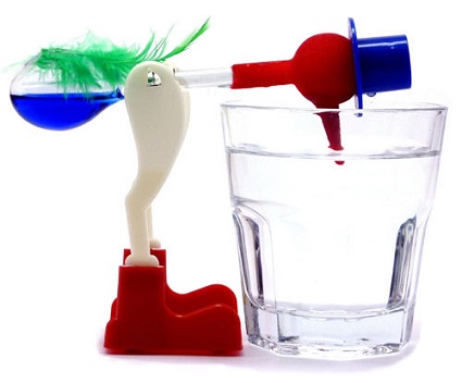
You know that little red guy that bobs in and out of a glass of water, seemingly without end? He’s an example of a non-perpetual motion device, because even he will eventually come to a stop due to something known as uncontrollable factors. Uncontrollable factors are a hindering factor in coal fired power plants, as well, most notably by a measure of efficiency known as heat rate.
Uncontrollable Factors At Play
The term heat rate is industry jargon for gauging how efficiently a coal fired power plant is operating. We previously learned that heat rate can be affected by things like missing thermal insulation on pipes and equipment. Of course missing insulation can easily be corrected because it’s directly under human control, but heat rate can be affected by many factors we can’t do anything about, known as uncontrollable factors.
Human fallibility is behind the phenomenon of uncontrollable factors, and because we are less than 100% accurate and efficient, so is anything that we make. At their best utilitycoal fired power plantshave an overall efficiency of between 30 and 40 percent, which means 60 to 70 percent of the stored energy inside coal is wasted and doesn’t go towards generating electricity.
Unfortunately there’s nothing we can do to eliminate these waste factors until improvements are made in the present level of technology. When we look through a microscope to view microbes we’re limited by the accuracy of the equipment, and in a similar way we are limited in everything we do as humans by the equipment we’ve built. That includes energy efficiency within power plants.
We’ll start identifying the uncontrollable factors that affect power plant performance next time.
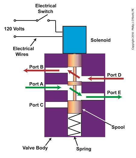
Previously, we looked at the components of a solenoid valve, which is an electro-mechanical device that is commonly used by engineers to operate pneumatic actuators with compressed air. These solenoid valve components include a solenoid and a valve body. We also looked at an illustration of an example solenoid valve. Its valve body had five ports for connections to compressed air pipes. Now, let’s see how the example solenoid valve operates to create different compressed air flow paths between its ports.
When the solenoid valve’s electrical switch is opened, the flow of electrical current from its 120 Volt supply is interrupted. This results in the solenoid’s wire coil being de-energized. As such, the coil generates no magnetic field. Without the magnetic field, there is no downward force exerted on the solenoid’s plunger and the valve body’s spool. A spring at the bottom of the valve body acts upon the spool to force it upward in the valve body and hold it there. With the spool in the upward position, two compressed air flow paths are created in the valve body. One path extends through a passageway connecting Ports D and B, and the other extends through a passageway connecting Ports A and E. The spool seals off the passageway leading to Port C.
The Solenoid Valve’s Operation: De-energized
When the electrical switch is closed, the 120 Volt supply is connected to the valve’s solenoid. This results in the solenoid’s coil becoming energized. When that happens, the electrical current flowing through the coil generates a magnetic field. The magnetic field forces the plunger and spool in the downward direction. The spool overcomes the spring force and moves into a downward position within the valve body. In this position, the spool creates a new pair of compressed air flow paths. These paths remain as long as the current flows through the solenoid’s coil. One compressed air flow path extends between Ports A and D. The other path extends between Ports E and C. The spool seals off the passageway leading to Port B.
The Solenoid Valve’s Operation: Energized
When the electrical switch opens, the solenoid’ coil again becomes de-energized. The magnetic field collapses, and no downward force remains on the plunger and spool. The spring forces the spool back up in the valve body. Once again, a pair of compressed air flow paths is created between Ports D and B, and between Ports A and E. The passageway to Port C is sealed off by the spool.
Next time, we’ll see how the example solenoid valve’s operation is applied to move the piston back and forth in a depositor’s pneumatic actuator.
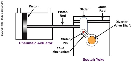
In my previous article, I introduced a mechanism known to engineers as a Scotch Yoke. It converts linear motion of a pneumatic actuator into rotary motion. With regard to the jelly filling depositor on a pastry production line, the Scotch Yoke converts the pneumatic actuator’s linear motion into the rotary motion needed to operate the depositor’s diverter valve. Now, let’s follow the Scotch Yoke’s motion in this application.
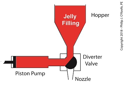
When the pneumatic actuator’s piston is all the way to the left, the Scotch Yoke’s slider is all the way to the left on the guide rod. The slider pin is at the top of the slot in the yoke mechanism. The diverter valve is positioned to create a path for the jelly so it can be emptied from the pump through the nozzle.
The Depositor’s Scotch Yoke Slider Is Full Left
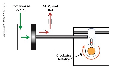
As compressed air is introduced to the left side of the actuator’s piston, the piston moves to the right, and the slider also moves to the right. As this happens, the slider pin begins to move in the yoke mechanism’s slot, and the diverter valve shaft begins to rotate clockwise.
The Depositor’s Scotch Yoke Clockwise Rotation
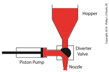
After the piston moves all the way to the right, and the diverter valve shaft stops its clockwise rotation. The diverter valve is positioned to create a path between the pump and hopper so the pump can suck in jelly from the hopper. When the pump is full of jelly, compressed air is introduced to the right side of the piston.
The Depositor’s Scotch Yoke Slider Is Full Right
As compressed air is introduced to the right side of the actuator’s piston, the piston moves to the left, and the Scotch Yoke’s slider also moves to the left. As this happens, the slider pin begins to move in the yoke mechanism’s slot, and the diverter valve shaft begins to rotate counterclockwise.
The Depositor’s Scotch Yoke Counterclockwise Rotation
After the piston moves all the way to the left, the diverter shaft stops its counterclockwise rotation. The diverter valve is once again positioned to create a path so the jelly can flow from the pump through the nozzle. After all the jelly is emptied from the pump, compressed air is introduced to the left side of the piston to repeat the previously described motion.
But what selectively admits compressed air to either the right or left of the pneumatic actuator’s piston? Next time, we’ll find out when we discuss a device called a solenoid valve.
Last time, we learned how a pneumatic actuator was connected to a depositor’s positive displacement piston pump so that it could extract jelly filling from a hopper, and deposit it through a nozzle onto a passing pastry. The pneumatic actuator imparted linear motion to the pump during this process. Since the pistons in the actuator and pump both move in a straight line, it was very easy and straightforward to connect the actuator to the pump.
For the depositing process to work, we must have an additional actuator to rotate the diverter valve as the pump operates. The valve changes the flow path of the jelly between the hopper and the nozzle. More specifically, the valve must rotate clockwise to create a flow path between the hopper and the pump while the pump extracts jelly from the hopper.
The Diverter Valve Rotated Clockwise
When the pump is full of jelly, the diverter valve must rotate counter-clockwise to create a flow path between the pump and the nozzle. This path allows the pump to empty its contents trough the nozzle.
The Diverter Valve Rotated Counter-Clockwise
Although the diverter valve’s motion is rotary, it can be operated with the linear motion of a pneumatic actuator. To convert the linear motion of the actuator to the rotary motion needed to operate the valve, we can employ a device known to engineers as a Scotch Yoke.
The Depositor’s Scotch Yoke
In the Scotch Yoke, the pneumatic actuator’s piston rod is connected to a slider. As the piston moves back and forth in the pneumatic actuator, the slider is free to move back and forth along a fixed guide rod. A pin is located on the slider. The pin loosely engages a slot in the yoke mechanism. As the slider moves, the pin can move freely in the slot. The yoke mechanism is rigidly attached to the rotating diverter valve shaft.
Next time, we’ll look at the rotary motion of the Scotch Yoke as the pneumatic actuator piston moves to the right and then to the left during the jelly depositing process.
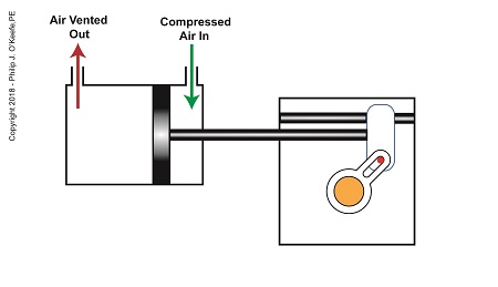
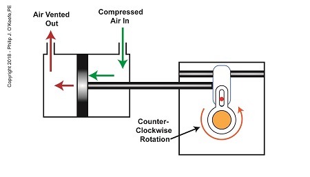
Last time we learned that a fruit jelly depositor in a food manufacturing plant is an example of a positive displacement pump at work. Today we’ll see how pieces of equipment on the depositor, known as a pneumatic actuators, work. Pneumatic actuators do not come in contact with the jelly flowing through the depositor. In other words, no jelly flows through the actuators. The jelly only flows through the transfer valve and positive displacement pump as we saw last time. The pump and valve can’t move by themselves. So, they need some device to set them in motion. That’s where the pneumatic actuators come into play. They impart movement to the pump and transfer valve to get the jelly flowing from the hopper and down through the nozzle and onto the pastry.
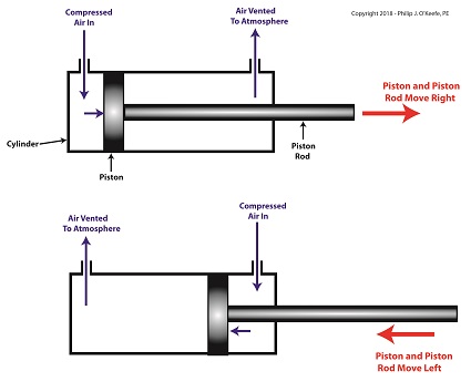
A pneumatic actuator is a device that operates using compressed air. Compressed air, from an external air compressor, enters into a tube in the actuator known as a cylinder. Inside the cylinder is a piston that can move along the length of the tube. Attached to the piston is a piston rod which extends to the outside of the cylinder.
When compressed air is introduced into the cylinder on the left side of the piston, it forces the piston and piston rod to move towards the right side of the cylinder. But, air must be vented out to atmosphere from the right side of the piston for this movement to occur. If no venting took place, trapped air to the right of the piston will get squeezed between the piston and the right end of the cylinder. When the air gets squeezed, it becomes pressurized. The pressure will impede the movement of the piston.
Likewise, when compressed air is introduced into the cylinder on the right side of the piston, it forces the piston and piston rod to move towards the left side of the cylinder.
The Depositor’s Pneumatic Actuator
So, depending on which end compressed air is admitted to the pneumatic actuator’s cylinder, the piston rod will move to the left or the right. In engineering terms, the actuator imparts linear motion to machines. In other words, the piston rod moves back and forth in a straight line.
Next time, we’ll see how the pneumatic actuator is connected to the depositor’s pump to impart the linear motion that draws jelly from the supply hopper and sends it streaming out of the nozzle onto a passing pastry.
Last time we learned that the human heart functions as the greatest of all positive displacement pumps, moving a set quantity of blood through it at precise intervals during its operating cycle. Today we’ll begin our exploration into how positive displacement pumps are used in industry, specifically within a food manufacturing plant.
At one point in my career I was employed as a design engineer in a food manufacturing plant. The plant was owned by the leading manufacturer of bakery products in the United States, responsible for supplying restaurants, bakeries, and grocery stores with finished and partially finished pastry goods that they would then resell. The plant produced vast amounts of puff pastry dough products, all of which were formed and filled with various fillings while zipping along on a production line conveyor belt. One of the products was a fruit filled pastry in which the belt moved so quickly, depositing fruit fillings into the dough by hand would be impossible, resulting in a frenzied mess similar to what Lucy encountered when she worked in a candy factory.
Clearly, an automated machine would work better in this and other scenarios. We’ll see how one known as a depositor functions on a food pastry line next time.
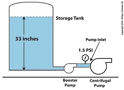
In our last article, we looked at an example problem involving a cavitating centrifugal pump that was drawing water from a storage tank. The bottom of the storage tank was sitting at the same level as the centrifugal pump’s inlet. The water level in the tank could not be increased to raise the pump inlet pressure, and thus eliminate the cavitation. So, the problem was solved by elevating the tank with respect to the pump inlet. Okay, what if the tank could not be elevated? How do we stop the centrifugal pump from cavitating? Well, we can install a booster pump between the tank and the centrifugal pump.
A booster pump is, as its name implies, a special kind of pump that is used to boost, or raise, water pressure flowing in a pipe. With regard to our example problem in the preceding article, the cavitating centrifugal pump inlet water is at 108ºF and a pressure of 1.2 pounds per square inch (PSI).
Reducing Cavitation With A Booster Pump — Before
Referring to the thermodynamic properties of water as found in tables appearing in engineering texts, we determine that if we keep water temperature at 108ºF but raise the pressure at the pump inlet from 1.2 PSI to 1.5 PSI we can stop the centrifugal pump from cavitating. We can install a booster pump to boost the pressure by the required 0.3 PSI and say goodbye to our cavitation problems.
Reducing Cavitation With A Booster Pump — After
This wraps it up for our series on cavitation in pumps. Next time, we’ll begin learning about some different topics.
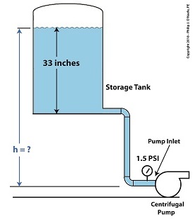
Last time we learned that the risk of damaging cavitation bubbles forming at a centrifugal pump’s inlet can be eliminated by simply increasing the water level inside the tank. Today we’ll do the math that demonstrates how reducing cavitation can be accomplished by raising tankelevation.
Reducing Cavitation by Raising Tank Elevation–Before
In our example we’ll suppose that we’re having a problem with cavitation bubbles forming at the inlet, where water temperature is 108ºF and water level inside the tank stands at 33 inches. We are using the formula,
So, the weight of the water in the tank exerts a pressure of 1.2 pounds per square inch (PSI) at the bottom of the tank and the pump inlet when it sits at the same elevation as the tank.
We know that if we increase the water depth in the tank relative to the pump inlet, we can raise the pressure at the pump inlet in accordance with equation (1). Raising the pressure will eliminate the cavitation bubbles that can form there. But, our tank is of fixed volume, and we can’t add more water to raise water depth beyond 33 inches. However, we can increase the elevation of the tank with respect to the inlet, which will produce the same effect. We’ll use equation (1) to determine the tank elevation, h, that will provide the needed increase.
Referring to the thermodynamic properties of water as found in tables appearing in engineering texts, we determine that if we keep water temperature at 108ºF but raise the pressure at the pump inlet from 1.2 PSI to 1.5 PSI, while maintaining current water depth in the tank, cavitation will cease. In other words, we need to increase P by 0.3 PSI.
Example of Reducing Cavitation by Tank Elevation–After
Plugging our known values into equation (1) we solve for h,
0.3 PSI = 0.036 pounds/inch3×h (3)
h = 0.3 PSI ÷ 0.036 pounds/inch3 (4)
h = 8.3 inches (5)
Cavitation will cease when we elevate the tank by 8.3 inches with respect to the pump.
Yet another means of increasing inlet pressure is to install a booster pump. We’ll talk about that next time.
Ever hear the old saying, “There’s more than one way to cook a goose”? The statement is meant to encourage creative thinking when problem solving. This forward thinking can be applied to the problem of destructive cavitation bubbles as well. Finding ways to reduce cavitation is something engineers are well versed in. As discussed in our last blog, one way to prevent cavitation is by lowering water temperature at a centrifugal pump’s inlet. But sometimes that isn’t possible. Today we’ll discuss another way, reducing cavitation by increasing water pressure.
One way to Reduce Cavitation by Increasing Water Pressure
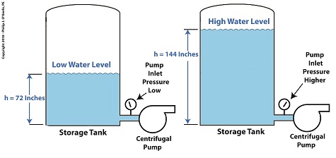
If you’ve ever seen a movie featuring divers, you’ll no doubt be aware that the deeper a diver goes, the more water pressure there is bearing down on him from above. The same goes for a centrifugal pump’s storage tank. The higher the water level inside the tank, the higher the pressure bearing down on the pump’s inlet, which is located at the bottom of the tank. This is the area in which cavitation bubbles are likely to form. The mathematical equation that illustrates this relationship is,
P = γ × h (1)
where, P is water pressure at the bottom of the tank, γ is the Greek symbol gamma, representing the specific weight of water, (0.036 pounds/inch3), and h is the depth of the water inside the tank.
Let’s see what happens when we increase the water level, h, from 72 inches, shown on the left, to 144 inches, on the right.
P = (0.036 Lb/in3) × (72 in) = 2.592 PSI (2)
When the water level is raised to 144 inches, P becomes,
P = (0.036 Lb/in3) × (144 in) = 5.184 PSI (3)
We see that by raising the water level in the tank from 72 to 144 inches, pressure at the bottom of the tank where the inlet is located is increased from 2.592 PSI to 5.184 PSI, pounds per square inch.
Next time we’ll see how simply elevating the tank has an impact on cavitation.
As we learned previously, cavitation bubbles form at a centrifugal pump’s inlet when the thermodynamic properties of water, namely temperature and pressure, are right. Today we’ll see how just manipulating water temperature can control cavitation.
Manipulating Water Temperature to Control Cavitation
Some centrifugal pumps draw water from an external heat source such as a heat exchanger in order to provide heat to buildings, generate power, and perform manufacturing processes. On some exchangers heat is applied at a fixed rate and can’t be varied. On others heat can be varied by using a heat exchanger fitted with a temperature control. This makes it easy to reduce or lower water temperature introduced at the pump’s inlet. If the temperature is kept low enough relative to the pressure at the inlet, cavitation bubbles won’t form.
Let’s say water enters the pump’s inlet from a heat exchanger at 59ºF and internal pump pressure is 0.25 pounds per square inch (PSI). With these parameters in place water boils and cavitation bubbles will form in the pump inlet. But if the heat exchanger is adjusted so that temperature is lowered by a mere two degrees to 57ºF, cavitation ceases. This is in accordance with the boiling points of water, listed for various pressures and temperatures, as published in engineeringthermodynamic texts.
If it’s not possible to lower water temperature at the pump inlet, an alternate method to control cavitation is to raise water pressure, which can be accomplished in different ways. We’ll review those options next time.