Posts Tagged ‘engineering’
Wednesday, February 21st, 2018
|
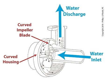
Last time we learned how centrifugal pumps can create a low pressure environment at the pump’s inlet, which can allow water inside the pump to boil at temperatures far lower than normal. Ultimately, this results in the formation of tiny but destructive cavitation bubbles. Today we’ll see how a centrifugal pump’s curved features are key to its functionality.
A Centrifugal Pump’s Curved Features are Key to Functionality
Even a casual glance at a centrifugal pump will disclose its many curved features. As the illustration shows, both the housing and internal impeller blades, are curved. These curves are known as volutes. The volutes’ dimensions are mathematically generated by engineers to facilitate the precise flow of water from inlet to discharge by way of the pump’s impeller blades.
Next time we’ll see how a centrifugal pump is home to both low and high water pressure, creating a volatile environment in which cavitation bubbles form and collapse.
opyright 2018 – Philip J. O’Keefe, PE
Engineering Expert Witness Blog
____________________________________ |
Tags: cavitation, centrifugal pump, engineering, flow, housing, impeller blades, volute
Posted in Engineering and Science, Expert Witness, Forensic Engineering, Innovation and Intellectual Property, Personal Injury, power plant training, Product Liability | Comments Off on A Centrifugal Pump’s Curved Features are Key to Functionality
Thursday, February 8th, 2018
|
Last time we performed an engineering experiment that demonstrated how we can lower the boiling point of water inside a lidded pot without applying heat if we use a vacuum pump to lower the pot’s internal pressure. We discovered that when pressure was lowered to 0.25 pounds per square inch (PSI), the water inside the pot turned to steam at a mere 59ºF, which initiated the cavitation process. Today we’ll see how centrifugal pumps can also create vacuums to initiate cavitation.
Centrifugal Pumps Can Create Vacuums
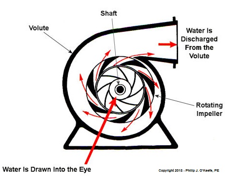
As we learned in a past blog, centrifugal pumps contain rotating impellers within a housing called a volute. This housing has an inlet, known as an eye, where water flows into the pump from a pipe, and an outlet, known as a discharge, where water flows out of the pump. The centrifugal pump creates a vacuum by mimicking the action of sucking soda through a straw. The spinning impeller draws water into the housing by creating low pressure at the inlet, and if the pressure gets low enough, we’ll recreate what happened in our vacuum pump and pot experiment. Water will boil at temps far lower than normal boiling point of 212 ºF. Just as in our experiment, if pressure is lowered to 0.23 PSI, water present at the pump inlet will boil at 59ºF, causing thousands of tiny steam bubbles to form and the pump to cavitate.
They’re just tiny bubbles, so what harm can they do? We’ll find out next time.
opyright 2018 – Philip J. O’Keefe, PE
Engineering Expert Witness Blog
____________________________________ |
Tags: boiling water, cavitation, centrifugal pump, engineering, low pressure, pump, vacuum
Posted in Engineering and Science, Expert Witness, Forensic Engineering, Innovation and Intellectual Property, power plant training, Product Liability | Comments Off on Centrifugal Pumps Can Create Vacuums
Monday, January 15th, 2018
|
Last time we introduced the phenomenon of cavitation, which simply stated is the rapid formation and collapse of vapor bubbles within liquids. It’s a destructive force that eats away at the metal parts of water pumps, used in power plants and other industrial settings. To understand how cavitation comes into play, we’ll explore a branch of engineering known as thermodynamics.
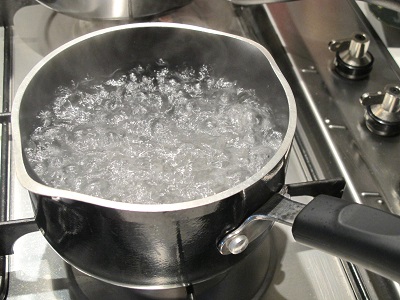
Cavitation doesn’t occur in a glass of water resting on a counter, but bring that water to a boil and the cavitation process will begin. That’s because cavitation is initiated when liquids change form from one physical state to another, in this case from a liquid to a vapor we commonly call steam. All liquids exist in three states, namely solid, liquid, and vapor, but in our thermodynamic analysis we’ll only consider two, liquid and vapor, because cavitation can’t occur in solids.
Thermodynamic Properties of Water and Cavitation
At normal atmospheric pressure of 15 pounds per square inch (PSI) which exists in the average kitchen, water remains in a liquid state between the temperatures of 32ºF and 212ºF. Above 212ºF water begins to boil, transforming into steam vapor. The state in which water exists depends on two thermodynamic properties, namely temperature and pressure. Change one of these variables and it affects the other, and thereby the conditions under which cavitation will occur.
We’ll take an in-depth look at this next time when we revisit the topics of pressurization and vacuums.
opyright 2018 – Philip J. O’Keefe, PE
Engineering Expert Witness Blog
____________________________________ |
Tags: cavitation, engineering, power plants, pumps, states of water, thermodynamics
Posted in Engineering and Science, Expert Witness, Forensic Engineering, Innovation and Intellectual Property, Personal Injury, power plant training, Product Liability | Comments Off on Thermodynamic Properties of Water and Cavitation
Wednesday, January 3rd, 2018
|
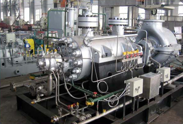
Shortly after I graduated with my engineering degree I worked as a power plant engineer at an electric utility. One day I was walking through the plant and heard a loud racket coming from the boiler feel pumps. These are the massive centrifugal pumps that deliver pressurized water to the boiler. The water is transformed into steam to drive steam turbines and spin electrical generators, which ultimately results in electrical power. The noise was so loud, it sounded like rocks were being ground up. I asked a coworker what was going on, and he replied matter-of-factly, “The pumps are cavitating.”
Boiler Feed Pumps Experience Cavitation
So what exactly is cavitation? We’ll find out next time when we explore the mechanics of this noisy phenomenon as it applies to boiler feed pumps and other centrifugal pumps.
opyright 2017 – Philip J. O’Keefe, PE
Engineering Expert Witness Blog
____________________________________ |
Tags: boiler, boiler feed pumps, cavitation, centrifugal pump, electric utility, electrical generator, engineering, power plant, steam turbine
Posted in Engineering and Science, Expert Witness, Forensic Engineering, Innovation and Intellectual Property, Personal Injury, power plant training, Product Liability | Comments Off on Boiler Feed Pumps Experience Cavitation
Thursday, December 21st, 2017
|
Last time we had a look inside a marvelous piece of engineering machinery known as a crankshaft. It plays a key role in converting the reciprocating linear motion of a steam driven engine into the rotary motion required to power externally mounted devices that are attached to it. Today we’ll finish up our blog series on flywheels when we see how using one in conjunction with a crankshaft facilitates a more even transmission of energy. Reciprocating engines maximize efficiency when they employ flywheels.
We learned that the energy in the steam supply decreases as the piston moves in its cylinder, which means a concurrent decrease in the engine’s horsepower and its ability to power machinery. Without an intervening action, the reciprocating steam engine would stall. Now, let’s see how adding a flywheel to the crankshaft can solve the problem.
Reciprocating Engines Maximize Efficiency When They Employ Flywheels
As we’ve learned before, a flywheel stores up kinetic energy while the engine powering it is performing at full horsepower, but if that power should drop off or cease to be produced, the flywheel gives up the kinetic energy stored inside it so as to keep externally mounted machinery operating until that stored energy is exhausted. This is all made possible because flywheels are designed to have moments of inertia sufficient to positively contribute to its storage of kinetic energy. This inertia is a numerical representation of the flywheel’s resistance to change in motion. Please review our past blog on the subject to refresh your memory.
The overall effect is that while the engine is operating, there’s an even flow of energy between the engine and flywheel and horsepower is supplied to keep machinery mounted to the crankshaft operating. Any diminishment in the power supplied will be compensated for by the flywheel’s stored kinetic energy.
Next time we’ll introduce a new topic, a phenomenon known as cavitation.
opyright 2017 – Philip J. O’Keefe, PE
Engineering Expert Witness Blog
____________________________________ |
Tags: crankshaft, efficiency, engineering, flywheel, horsepower, kinetic energy, moment of inertia, reciprocating steam engine
Posted in Engineering and Science, Expert Witness, Forensic Engineering, Innovation and Intellectual Property, Personal Injury, Product Liability | Comments Off on Reciprocating Engines Maximize Efficiency When They Employ Flywheels
Friday, December 15th, 2017
|
Last time, we learned that a crankshaft is an engineering device which converts the reciprocating linear motion of an engine’s back-and-forth moving piston into the rotary motion that powers externally attached machinery. Its movement is shown here,
A Crankshaft in Motion
We’ll see how a crankshaft and piston’s motion benefits by the use of a flywheel next time.
opyright 2017 – Philip J. O’Keefe, PE
Engineering Expert Witness Blog
____________________________________ |
Tags: crankshaft, cylinder, engine, engineering, flywheel, machinery, piston, reciprocating linear motion, rotary motion
Posted in Engineering and Science, Expert Witness, Forensic Engineering, Innovation and Intellectual Property, Personal Injury, Product Liability | Comments Off on A Crankshaft in Motion
Wednesday, December 6th, 2017
|
Last time we developed an engineering formula to calculate the horsepower required to accelerate a flywheel by way of a reciprocating steam engine, which contributes to the storage of kinetic energy inside a flywheel. Today we’ll gain a clearer understanding of how this works when we take a look inside a reciprocating steam engine.
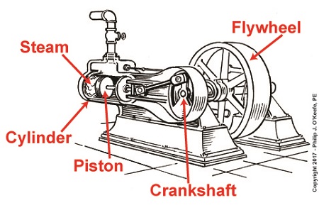
A Look Inside a Reciprocating Steam Engine
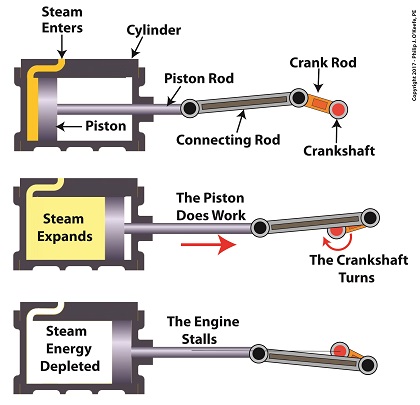
A reciprocating steam engine performs the work of transforming steam’s heat energy into the mechanical energy needed to move a piston contained within a cylinder. During a complete operating cycle this piston travels from one end of the cylinder to the other, then back again. This is made possible because during the first half of the cycle pressurized steam enters one end of the cylinder and expands inside it, forcing the piston to move.
This process inside the cylinder results in movement of a piston that’s attached to a piston rod, which in turn is connected to a crankshaft via a connecting rod and crank rod. The crankshaft is a device which converts the reciprocating linear motion of an engine’s piston into rotary motion and in so doing facilitates the powering of any externally mounted rotating machinery attached to it. So long as there’s ample steam to power the internal piston, over time, energy in the form of horsepower will be available to externally mounted devices. The energy in the steam decreases as the steam expands behind the moving piston. So, the engine’s horsepower, will decrease as the piston travels to the end of the cylinder. If the energy in the steam should become depleted, the reciprocating steam engine will stall. The engine will no longer be able to perform work.
Next time we’ll see how a crankshaft works when we take a look inside it.
opyright 2017 – Philip J. O’Keefe, PE
Engineering Expert Witness Blog
____________________________________ |
Tags: connecting rod, crank rod, crankshaft, energy, engineering, flywheel, kinetic energy, piston rod, power, reciprocating steam engine, work
Posted in Engineering and Science, Expert Witness, Forensic Engineering, Innovation and Intellectual Property, Personal Injury, Product Liability | Comments Off on A Look Inside a Reciprocating Steam Engine
Friday, November 24th, 2017
|
Last time we discussed how torque is created as a flywheel spins. This torque is a factor of the flywheel’s moment of inertia, which is dependent on how far the masses of the flywheel’s parts are located from its center of rotation. Today we’ll present a formula to compute how much horsepower is required to accelerate a flywheel. And here it is,

Horsepower Required to Accelerate a Flywheel
where, T is the torque created on the flywheel’s shaft in units of inch-pounds. The term n is the flywheel shaft’s speed of rotation in revolutions per minute, RPM. Horsepower, HP, is engineering shorthand for a unit of power equal to 6600 inch-pounds per second, and the number 63,025 is a constant needed to convert torque, T, and the spinning shaft’s rotations per minute, RPM, into horsepower units.
Torque is present whether the flywheel’s spin accelerates or decelerates. During acceleration torque is created, which contributes to the production of kinetic energy that’s stored inside the flywheel. When a flywheel’s spin decelerates, its mass experiences the effects of negative acceleration, and stored kinetic energy is released.
As we learned awhile back, horsepower is a function of torque in any moving machinery, including engines and flywheels. An engine must produce horsepower to accelerate a flywheel connected to its shaft. By the same token, when the engine’s horsepower output diminishes or stops, the flywheel begins to decelerate. This deceleration causes kinetic energy stored within the flywheel to be released, providing horsepower necessary to keep the engine and flywheel spinning. That is, until the power output of the engine returns or the stored kinetic energy of the flywheel is ultimately exhausted.
We’ll see how that works next time when we take a look inside a reciprocating engine.
opyright 2017 – Philip J. O’Keefe, PE
Engineering Expert Witness Blog
____________________________________ |
Tags: acceleration, deceleration, engine, engineering, flywheel, horsepower, kinetic energy, mass, moment of inertia, torque
Posted in Engineering and Science, Expert Witness, Forensic Engineering, Innovation and Intellectual Property, Personal Injury, Product Liability | Comments Off on Horsepower Required to Accelerate a Flywheel
Monday, November 13th, 2017
|
Last time we began our discussion on moment of inertia and how it affects a flywheel’s storage of kinetic energy. That inertia is a function of the flywheel’s mass, in particular how the mass is distributed. Today we’ll continue our discussion and see how an engineering principal known as torque affects things.

Flywheel Torque and Distribution of Mass
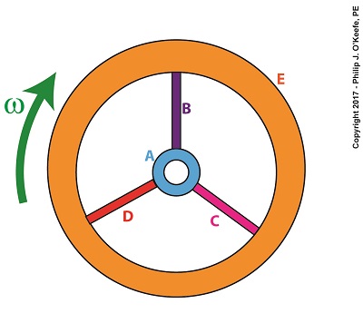
We learned in a previous blog that torque is most simply defined as a measure of how much force acts upon an object to cause it to rotate around a pivot point or center of rotation, shown as a small black dot in the illustration. For our discussion we’ll focus on two parts of the flywheel, the hub, part A, and the rim, part E.
Part A has a mass mA located a distance rA from the flywheel’s center, while part E has a mass mE located a distance rE from it. When an engine applies mechanical power to the flywheel by way of its rotating shaft, the revolutions per minute, RPM, increase and along with it the angular velocity, ω, also increases. For a refresher on this, follow the link.
Because of this relationship, we can calculate the kinetic energy contained within a flywheel using the kinetic energy formula,
KE = ½ × ∑[m × r2] × ω2 (1)
As the flywheel’s angular velocity increases or decreases in response to the engine’s energy output, parts A and E reflect acceleration or deceleration of aA and aE. Since parts A and E exhibit both mass and acceleration, they are subject to Newton’s Second Law of Motion, which states that force equals mass times acceleration. Using that relationship we can calculate the force exerted on each part by,
FA = mA × aA (2)
FE = mE × aE (3)
Part A is small compared to part E, therefore mE is greater than mA and accordingly FE is greater than FA. Forces FA and FE act as torques, because they cause parts A and E to rotate around the flywheel’s center of rotation, so they are designated as Torque A, TA, and Torque E, TE. These torques are computed by,
TA = FA × rA (4)
TE = FE × rE (5)
Part E’s greater mass will contribute more torque than part A, and it will also contribute more to the flywheel’s kinetic energy content.
Most flywheels are designed with heavy rims supported by small hubs and slender spokes, because the more mass that’s distributed away from the flywheel’s center of rotation, the greater the flywheel’s moment of inertia and torque, and the more kinetic energy it can store.
Next time we’ll develop an equation which allows us to quantify the horsepower required to accelerate a flywheel.
opyright 2017 – Philip J. O’Keefe, PE
Engineering Expert Witness Blog
____________________________________ |
Tags: distribution of mass, engineering, flywheel, kinetic energy, mass, moment of inertia, torque
Posted in Engineering and Science, Expert Witness, Forensic Engineering, Innovation and Intellectual Property, Personal Injury, Product Liability | Comments Off on Flywheel Torque and Distribution of Mass
Monday, November 6th, 2017
|
Last time we arrived at a general formula to compute the kinetic energy, KE, contained within the totality of a spinning flywheel made up of numerous parts. Today we’ll discuss the terms in that formula, which encompasses a phenomenon of flywheels known as moment of inertia.
Moment of Inertia in a Flywheel
The kinetic energy formula we’ve been working with is, again,
KE = ½ × Σ[m × r2] × ω2 (1)
The bracketed part of this equation makes reference to spinning flywheels comprised of one or more parts, and that’s what we’ll be focusing on today. The symbol Σ is the Greek letter sigma, standard engineering shorthand notation used to represent the sum of all terms and mathematical operations contained within the brackets.
Our illustration shows we have five parts to consider: a hub, three spokes and a rim, and label them A, B, C, D, and E respectively. Each part has its own mass, m, and is a unique distance, r, from the flywheel’s center of rotation. The flywheel’s angular velocity is represented by ω.
For our flywheel of parts A through E our expanded equation becomes,
Σ[m × r2] = [mA × rA2] + [mB × rB2] + [mC × rC2] + [mD × rD2] + [mE × rE2] (2)
Equation (2) represents the sum total of moments of inertia contained within our flywheel. It’s a numerical representation of the flywheel’s degree of resistance to changes in motion.
The more mass a flywheel has, the greater its moment of inertia. When at rest this greater moment of inertia means it will take more effort to return it to motion. But once in motion the flywheel’s greater moment of inertia will make it harder to stop. That’s because there’s a lot of kinetic energy stored within its spinning mass, and the heavier a flywheel is, the more kinetic energy it contains. In fact, for any given angular velocity ω, a large and heavy flywheel stores more kinetic energy than a smaller, lighter flywheel.
But there’s more to a flywheel’s moment of inertia than just mass. What’s really important is how that mass is distributed. We’ll get into that next time when we discuss torque.
Copyright 2017 – Philip J. O’Keefe, PE
Engineering Expert Witness Blog
____________________________________ |
Tags: angular velocity, center of rotation, engineering, flywheel, kinetic energy storage, mass, moment of inertia, spinning flywheel
Posted in Engineering and Science, Expert Witness, Forensic Engineering, Innovation and Intellectual Property, Personal Injury, Product Liability | Comments Off on Moment of Inertia in a Flywheel


